Shower head

a shower head and shower head technology, applied in the direction of spray nozzles, combustion types, lighting and heating apparatuses, etc., can solve the problem of uniform discharge of water from the plurality, and achieve the effect of uniform shower water, easy formation, and uniform cross-sectional area

Inactive Publication Date: 2008-04-29
OKUMA YOJI
View PDF18 Cites 88 Cited by
  • Summary
  • Abstract
  • Description
  • Claims
  • Application Information

AI Technical Summary

Benefits of technology

[0008]According to a first invention for attaining the above object, there is provided a shower head comprising: a shower head body having a cylindrical water passage and an inflected water passage connected to the cylindrical water passage, the passages being provided inside the shower head body from a proximal portion thereof having a water inlet through a head portion thereof; a sprinkler cap having a ring-shaped cap body and a sprinkler plate, the cap body having a fitting opening formed in a central portion of the cap body and being fixed to the head portion of the shower head body via a screw mechanism, the sprinkler plate having a plurality of sprinkler holes and being secured to the fitting opening; and a flow control member having a diameter-reduced water passage and being placed on an upstream side of the sprinkler plate; wherein the diameter-reduced water passage has a first water passage portion with a small diameter and a second water passage portion respectively provided on an entry side and an exit side of the diameter-reduced water passage, the first water passage portion having a cross-sectional area smaller than those of the cylindrical water passage and the inflected water passage of the shower head body, the second water passage portion having an inside diameter which is 1.5 to 3 times that of the first water passage portion; and a tapered diameter-reduced portion, reduced in diameter in a flow direction and communicated with the inflected water passage, is formed on an upstream side of the first water passage portion, and a diameter-increased portion increased in diameter in the flow direction is formed on a downstream side of the second water passage portion; whereby the flow control member reduces volume of water and generates substantially uniform water pressure distribution radially on an immediately upstream side of the sprinkler cap.
[0019]In the shower head according to the first to fourth inventions, the tapered diameter-reduced portion formed on the immediately upstream side of the first water passage portion preferably has an inside diameter of 1.6d to 2.3d on an entry side thereof, a length of 0.4d to 0.5d, and a taper angle (i.e., opening inclination angle to an axis of the diameter-reduced water passage, the same hereunder) of 30 to 45 degrees. Such a structure permits the water fed in the water passages of the shower head to be efficiently taken in the first water passage portion.

Problems solved by technology

Accordingly, the water is not impinged on the entire sprinkler plate evenly, and thereby the water is not uniformly discharged from the plurality of the sprinkler holes disposed in the sprinkler plate.

Method used


Image

  • Shower head
  • Shower head
  • Shower head

Examples


first embodiment

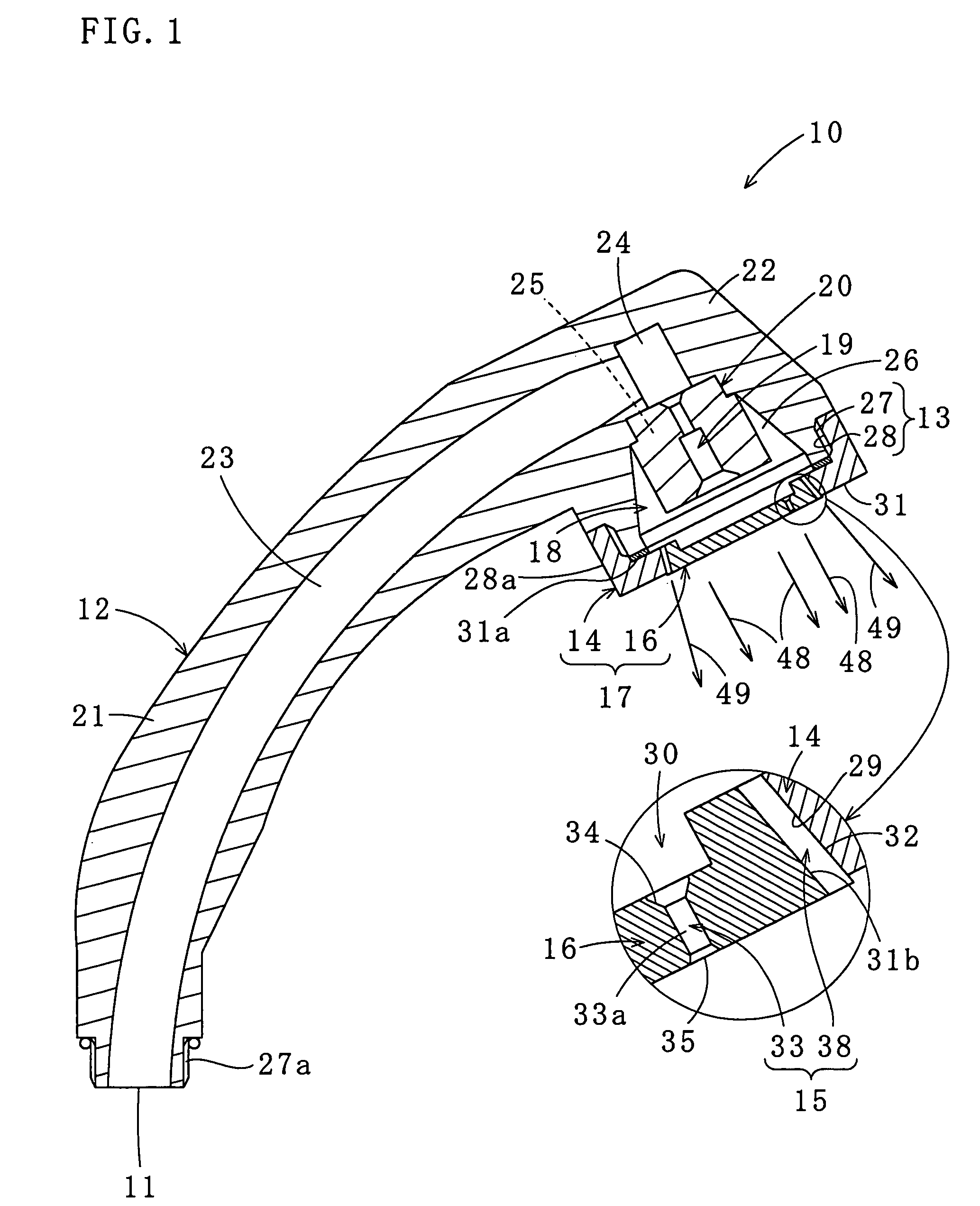
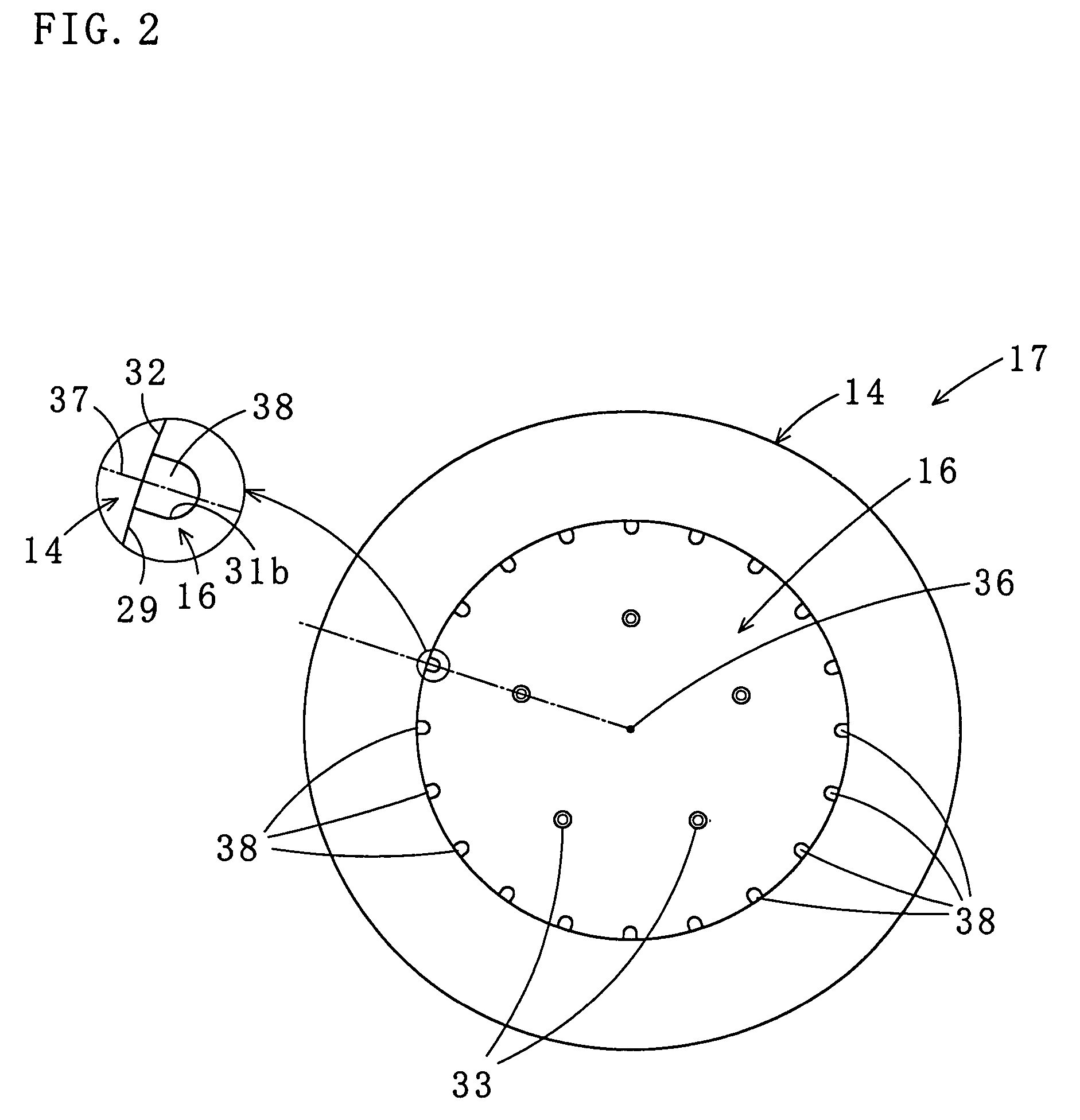
[0033]Referring to FIGS. 1-5 (C), a shower head 10 according to the present invention will be explained.

[0034]As illustrated in FIG. 1, the shower head 10 includes a shower head body 12 having a water inlet 11 provided at a proximal portion thereof; and a sprinkler cap 17 having a ring-shaped cap body 14 and a sprinkler plate 16, the cap body 14 being fixed to a head portion 22 of the shower head body 12 via a screw mechanism 13, the sprinkler plate 16 having a plurality of sprinkler holes 15 and being fitted in the cap body 14. A flow control member 20 having a diameter-reduced water passage 19 is disposed in space 18 located upstream of the sprinkler plate 16. According to the structure, the shower head 10 allows water (including mixed hot and cold water, the same hereunder) supplied from the water inlet 11 to be discharged from the sprinkler holes 15 in the sprinkler plate 16. The shower head 12, the sprinkler cap 17, and the flow control member 20 are made of such as an ABS resi...

second embodiment

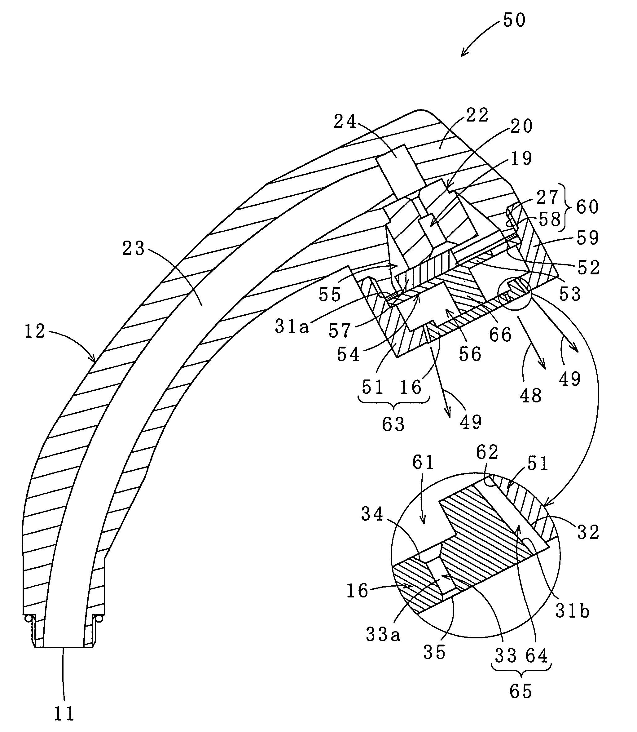
[0052]Referring to FIGS. 6 and 7, a shower head 50 according to the present invention is explained. The shower head 50 is employed when pressure of the water supplied from the water inlet 11 is high. The shower head 50 lowers the discharge pressure of the water while maintaining the volume of the water, and discharges shower water having appropriate discharge pressure on the user when the shower is used. The same elements as those of the shower head 10 are provided with the same numbers, and detailed explanation thereof is omitted.

[0053]The shower head 50 differs from the shower head 10 in the following points: (1) a side wall portion 59 of a cap body 51, which is screwed to the male screw 27 of the shower head body 12, is longer than the side wall portion 28a of the cap body 14 of the shower head 10; (2) a partition member 54 having a partition plate 53 provided with a through-hole 52 is disposed between the flow control member 20 and the sprinkler plate 16 so as to form a first ch...


PUM


Abstract

A water-saving type shower head operable to reduce flow volume while maintaining a high discharge pressure. A diameter-reduced water passage 19 of a flow control member 20 disposed in a head portion 22 of a shower head body 12 has a first and a second water passage portions 40 and 41 provided on an entry side and an exit side thereof, respectively. The first water passage portion 40 has a small diameter, and the second water passage portion 41 has an inside diameter which is 1.5 to 3 times that of the first water passage portion 40. On an upstream side of the first water passage portion 40, a tapered diameter-reduced portion 43 reduced in diameter in a flow direction is formed, and on a downstream side of the second water passage portion 41, a diameter-increased portion 45 increased in diameter in the flow direction is formed.

Description

BACKGROUND OF THE INVENTION[0001]1. Field of the Invention[0002]The present invention relates to a water-saving type shower head which is operable to reduce flow volume while maintaining a high discharge pressure of water discharged from the shower head.[0003]2. Description of the Related Prior Art[0004]A conventional shower head has a shower head body and a sprinkler plate which is provided with a number of small holes and disposed in a distal portion of the shower head body. The conventional shower head uses pressure of water (including mixed hot and cold water) supplied from a proximal side of the shower head to discharge water from the sprinkler plate. Accordingly, strength of the water discharged from the sprinkler plate, i.e. speed of the water spurt from the small holes in the plate, depends on water pressure inside the shower head body. If the water has pressure within a range of standard values of normal tap water pressure, the water is showered at sufficient speed. However...

Claims


Application Information

Patent Timeline
Patent Type & Authority Patents(United States)
IPC IPC(8): B05B9/08
CPCB05B1/18B05B7/2462A47K3/28B05B1/30E03C1/0409E03C1/08E03C2001/026
Inventor OKUMA, YOJI
Owner OKUMA YOJI
Why Eureka
Try Eureka