
Sensing and communication system and method

a communication system and data technology, applied in the field of data sensing and communication systems, can solve the problems of accelerating the fatigue of wires, and limiting the use and application

Active Publication Date: 2008-04-29
FIRESTONE IND PROD COMPANY
View PDF64 Cites 27 Cited by
  • Summary
  • Abstract
  • Description
  • Claims
  • Application Information

AI Technical Summary

Benefits of technology

The present patent describes a sensing and communication system for use on an associated structural member undergoing an external input. The system includes a transceiver and a transponder, with a sensor also being attached to the structural member. The sensor generates a signal in response to the external input and the transponder receives and modulates the electromagnetic wave in response to the sensor output signal. This allows for the determination of the input level of the external input. The system can be used in various applications such as vehicle suspension systems. The technical effects of this patent include improved sensing and communication capabilities for associated structural members, allowing for better monitoring and control of external inputs.

Problems solved by technology

Such devices, however, suffer from numerous disadvantages and problems which can, under some conditions, undesirably limit the use and application thereof.
These disadvantages are particularly salient in certain applications and in use on or with certain structural arrangements, such as arrangements that include relative movement between two components thereof, for example.
Unfortunately, known accelerometers normally include one or more wires to power the sensor and communicate signals and / or data.
This repeated flexing can undesirably result in breakage due to wire fatigue and / or other problems.
What's more, the wire is often undesirably exposed to environmental conditions and contaminants, such as dirt, water and salt, for example.
This can undesirably lead to degradation of the wire and / or insulation which can accelerate wire fatigue and breakage.
Additionally, the wire is subject to impacts from road debris, which can damage the wire and / or its connection to the sensor.

Method used


Image

  • Sensing and communication system and method
  • Sensing and communication system and method
  • Sensing and communication system and method

Examples


Embodiment Construction

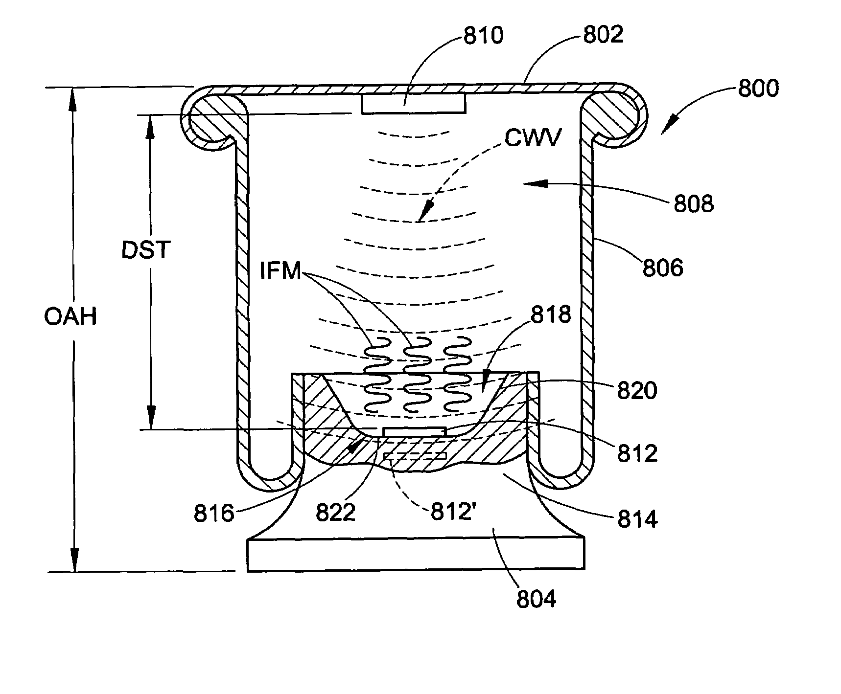
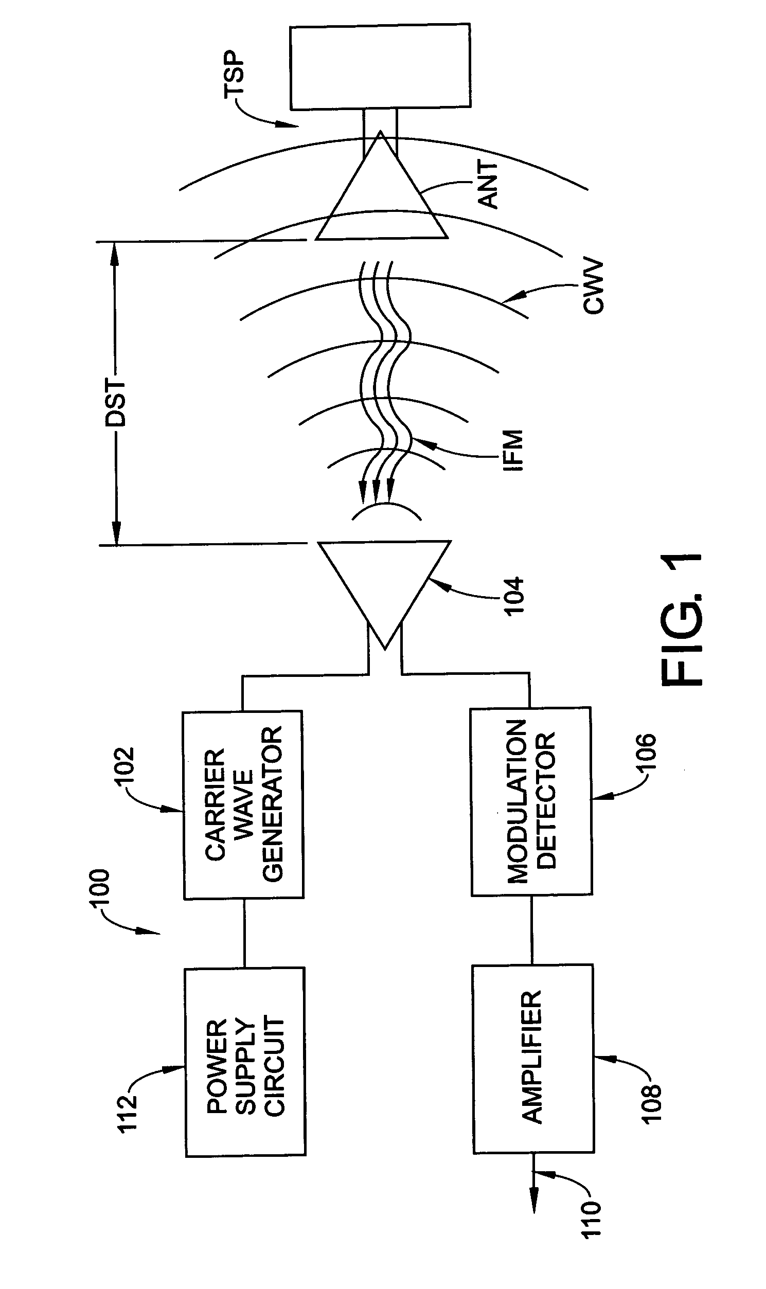
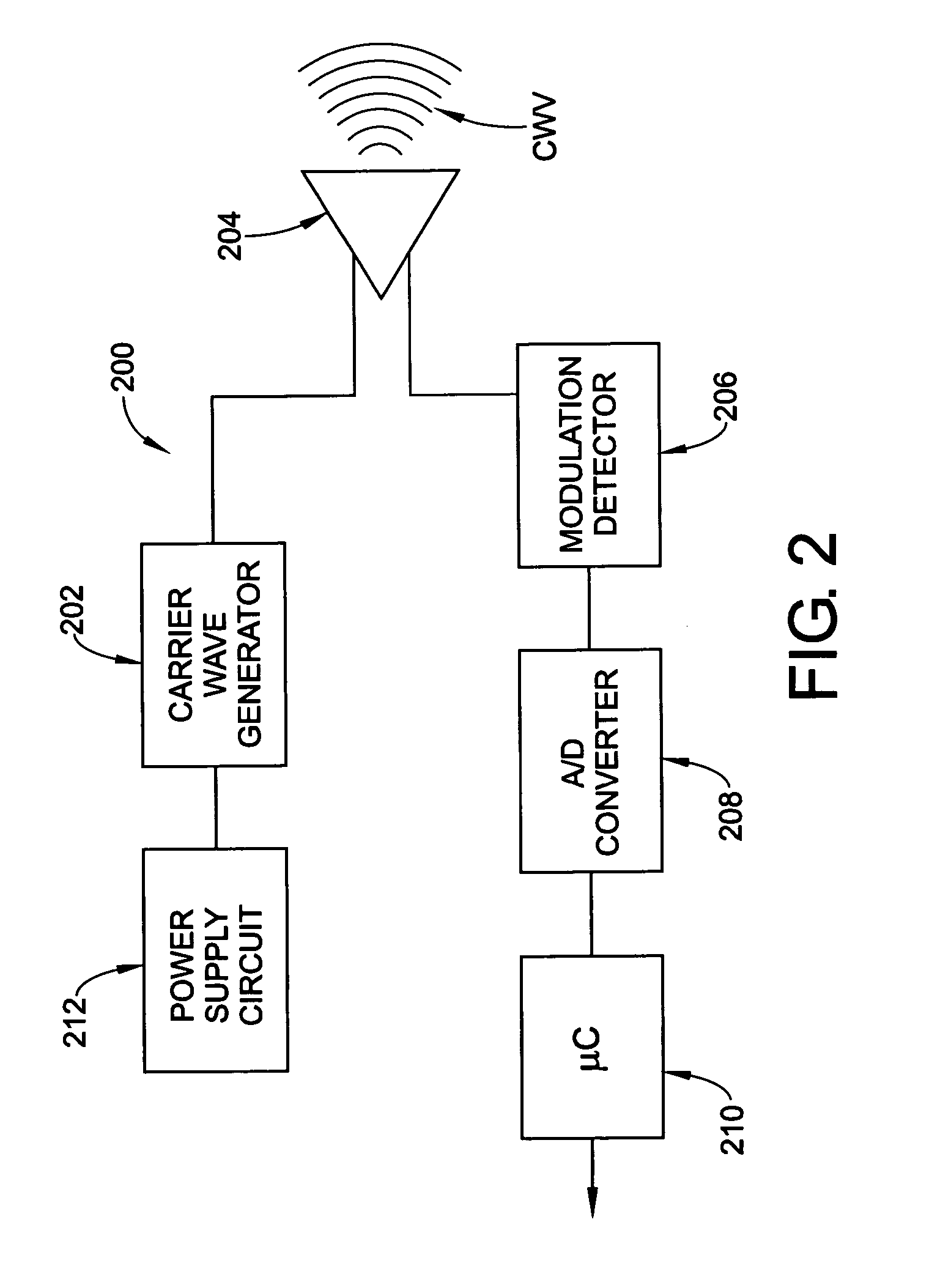
[0034]Referring now in greater detail to the drawings wherein the showings are for the purposes of illustrating preferred embodiments of the present novel system, apparatus and / or method only, and not for the purposes of limiting the same, FIG. 1 schematically illustrates a distance indicating system that includes a transceiver 100 in use with a transponder TSP that is spaced a distance DST from the transceiver. It will be appreciated that transponder TSP is merely representative of a suitable transponder cooperable with a transceiver, such as transceiver 100, and that the structure and operation of exemplary embodiments of suitable transponders will be discussed with more specificity hereinafter. Transceiver 100 is operable to broadcast an electromagnetic signal, such as an electromagnetic (EM) carrier wave CWV, for example, toward transponder TSP.

[0035]Transceiver 100 includes a carrier wave generator 102 in electrical communication with an antenna 104. Wave generator 102 is adapt...


PUM


Abstract

A sensing and communication system includes a transceiver broadcasting an electromagnetic wave, a transponder supported on an associated structural member at a distance from the transceiver that receives the electromagnetic wave, and a sensor adjacent the transponder and in communication therewith. The sensor being operable to sense an input acting on the associated structural member and communicate a signal corresponding to the input to the transponder. The transponder is adapted to induce a modulation of the electromagnetic wave in relation to at least one of the sensor signal and the distance between the transceiver and the transponder. A method is also disclosed.

Description

BACKGROUND[0001]The present novel concept broadly relates to the art of data sensing and communication systems and, more particularly, to a system and method for sensing an input or property of an associated structural member and communicating a signal substantially corresponding to the sensed input using electromagnetic carrier wave modulation.[0002]The subject system and method are amenable to broad use in a wide variety of applications and environments. One example of a suitable application is the use of the subject system and method on and with an associated fluid suspension member, such as an air spring of a vehicle, for example. The subject system and method will be discussed in detail hereinafter with specific reference to use on such an associated fluid suspension member. However, it is to be specifically understood that the subject system and method are capable of broader application and are not intended to be limited to this specific example of a suitable application.[0003...

Claims


Application Information

Patent Timeline
Patent Type & Authority Patents(United States)
IPC IPC(8): F16F9/04H04B5/48
CPCB60G17/01933F16F9/05F16F9/3292H04B5/02B60G2204/111B60G2400/252B60G2401/174B60G2500/30H04B5/0043H04B5/0068H04B5/45H04B5/73H04B5/48
Inventor NORDMEYER, DANIEL L.
Owner FIRESTONE IND PROD COMPANY
Learn More