Compression fitting for pipes

a compression fitting and pipe technology, applied in the direction of pipes/joints/fittings, hose connection arrangements, pipe connection arrangements, etc., can solve the problems of inconvenience presented, compromising the formation of joints, and the possibility of successive corrections, so as to improve the installation facility and ensure the reliability

Inactive Publication Date: 2008-04-29
ROMANELLI ANTONIO +2
View PDF15 Cites 22 Cited by
  • Summary
  • Abstract
  • Description
  • Claims
  • Application Information

AI Technical Summary

Benefits of technology

[0014]The aim of the present invention is to obviate the inconveniences of the known technique and to produce a pressure joint that is highly reliable both for mechanical resistance a

Problems solved by technology

When the fitting is intended to receive rigid or semi-rigid pipes, in plastic, metal or multi-layer metal and plastic, a problem is constituted by the need to achieve efficient resistance both to the withdrawal mechanical stress and to the hydraulic leakages, which is also reliable over its service life.
A serious inconvenience that is presented by this type of pressure joint known is constituted by the fact that their reliability is determined by the precision with which the sleeve pressed, in relation the configuration the internal element onto which the pipe is fitted.
Nevertheless, the application of these fittings to the ex

Method used


Image

  • Compression fitting for pipes
  • Compression fitting for pipes
  • Compression fitting for pipes

Examples


Embodiment Construction

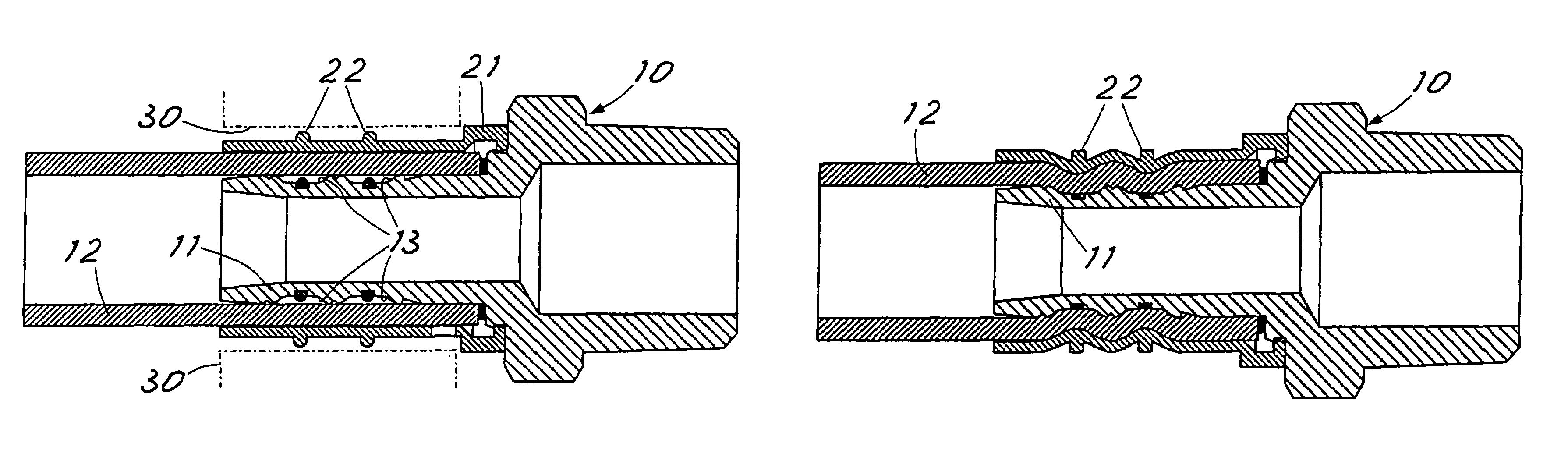
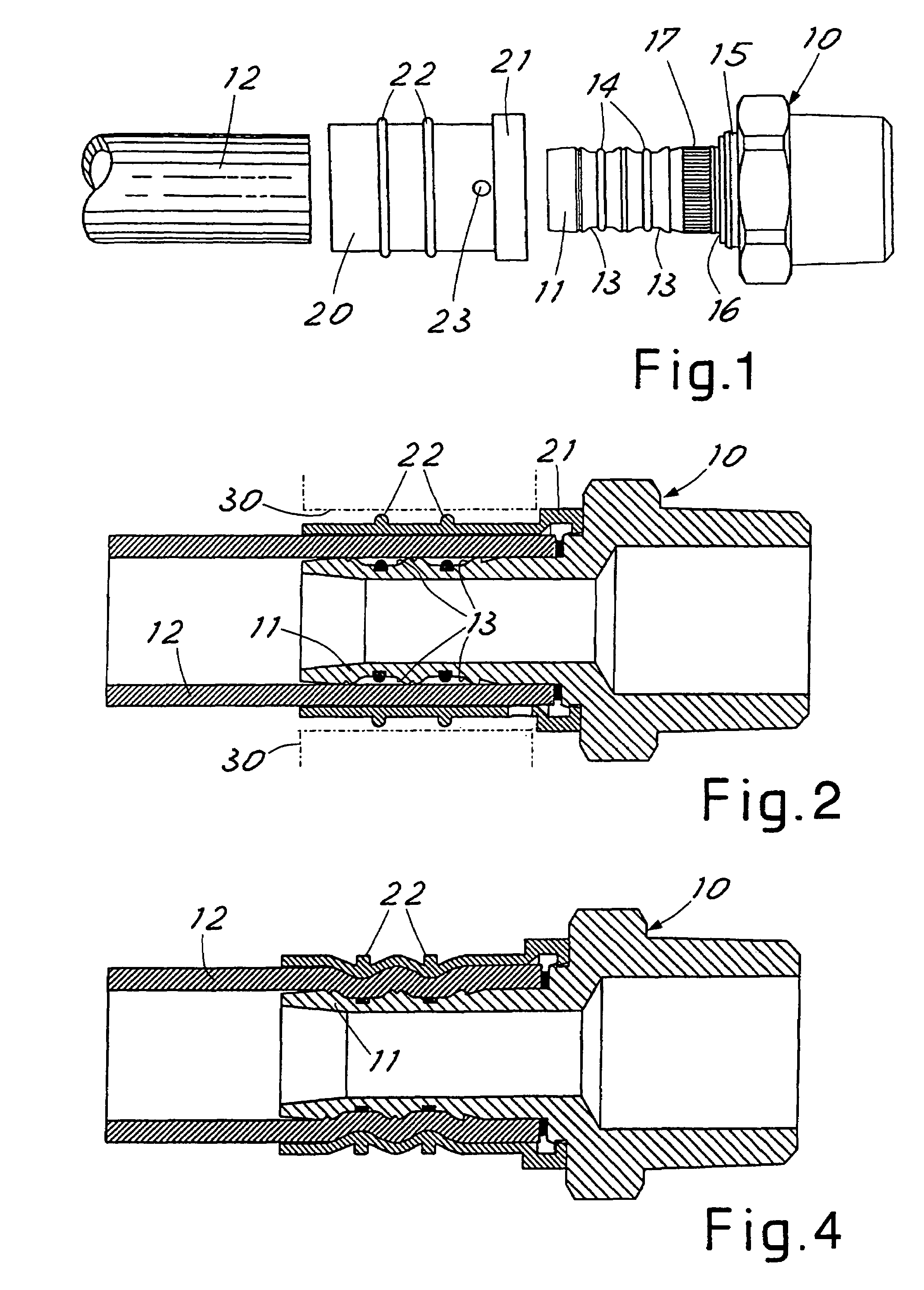
[0022]Referring to the drawings in particular, FIG. 1, the fitting in accordance with the invention comprises a body generically indicated with 10, of any configuration desired to be connected to another element that is not shown of a hydraulic plant.

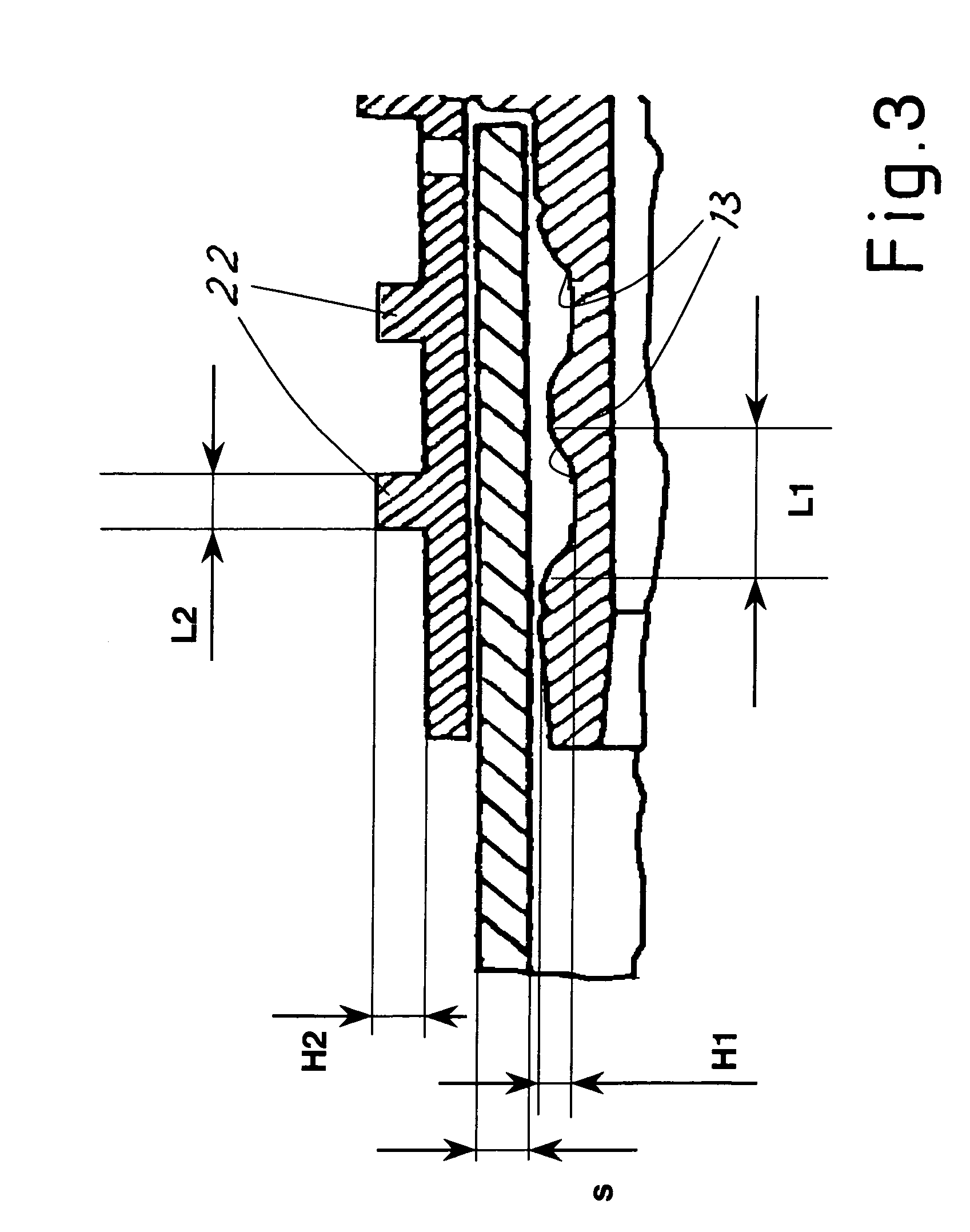
[0023]The element 11, onto which pipe 12 is intended to be fitted, comes out of the generic body 10. Element 11 presents a suitable number of grooves 13, in the example two.

[0024]A sleeve 20 is also provided which is intended to be inserted around the pipe fitted onto the element 11 until it comes up against a shoulder 16, as can be seen in FIG. 2.

[0025]Preferably, but not necessarily, an edge of the sleeve has a temporary holding axial coupling 21 on a complementary seat 15 of the corresponding extremity of the element 11. This coupling can be of simple interference with limited pressure, or the claw, filet, bayonet or similar type, and it is useful to fix the position of the sleeve when presetting the joint, so that accidental movemen...


PUM

PropertyMeasurementUnit
Thicknessaaaaaaaaaa
Diameteraaaaaaaaaa
Depthaaaaaaaaaa

Abstract

A compression fitting for rigid or semi-rigid pipes comprising an internal element 11 onto which the pipe 12 is fitted and into which at least one circumferential groove 13 is machined and an external sleeve 20 usually cylindrical is positioned around the pipe and intended to be deformed by radial compression to push the wall of the pipe inside said groove. The external wall of the sleeve 20 bears a circumferential protruding bead 22 in line with its area which is found in line with the groove of the internal element with interposition of the wall of the pipe, so that the compression of the sleeve by action of a cylindrical pressing wall 30 acts on the bead to deform the sleeve with the purpose of pushing the wall of the pipe inside the groove of the internal element.

Description

CROSS REFERENCE TO RELATED APPLICATIONS[0001]This application is a United States National Phase application of International Application PCT / EP03 / 14367 and claims the benefit of priority under 35 U.S.C. § 119 of M12003A 000010 filed Jan. 8, 2003, the entire contents of which are incorporated herein by reference.FIELD OF THE INVENTION[0002]The present invention pertains to a compression fitting for pipes.BACKGROUND OF THE INVENTION[0003]The fastening of the extremity of a pipe to a hydraulic connection terminal body, fitting the extremity onto an internal cylindrical element, then pressing the pipe on said element by means of radial deformation of an external sleeve is known.[0004]If the pipe is made in a pliable material, such as a plastic material, the use of an internal element generally cylindrical is known whose external surface has successive ridges and ring-like grooves. The pressure of the pipe on this sleeve deforms the material of the pipe making said ridges penetrate into ...

Claims


Application Information

Patent Timeline
IPC IPC(8): F16L33/00F16L33/207
CPCF16L33/2076
Inventor ROMANELLI, ANTONIOROMANELLI, CARMINEROMANELLI, MARIO
Owner ROMANELLI ANTONIO
Why Eureka
Try Eureka