Portable mounting device for mobile entertainment unit

a mobile entertainment unit and mounting device technology, applied in the direction of chairs, vehicle components, stools, etc., can solve the problems of not having one important feature, the user is almost impossible to hold the device for the entire duration, and the conventional supporting device, although useful, lacks one important feature, etc., to achieve maximum flexibility and comfort

Inactive Publication Date: 2008-04-29
ZHENG EDWARD
View PDF7 Cites 36 Cited by
  • Summary
  • Abstract
  • Description
  • Claims
  • Application Information

AI Technical Summary

Benefits of technology

[0010]A main object of the present invention is to provide a portable mounting device for a mobile entertainment unit which is adapted for detachably mounting the entertainment unit on two spacedly apart supporters, such as two head support extensions of a vehicle seat, in such a way as to impart maximum flexibility and comfort to those viewing the multimedia materials shown on the mobile entertainment unit.
[0011]Another object of the present invention is to provide a portable mounting device which is adapted to detachably mount a mobile entertainment unit at the back of a car's seat in such a manner that the mobile entertainment unit is capable of being adjusted to fit a particular viewing angle so as to serve a maximum number of viewers behind the car's seat.
[0012]Another object of the present invention is to provide a portable mounting device for mounting a mobile entertainment unit onto a car's seat, wherein the portable mounting device does not cause any surface destruction to the mobile entertainment unit as well as the car's seat, so that the present invention fits for widespread utilizations.
[0013]Another object of the present invention is to provide a portable mounting device which does not involves complicated mechanical components for performing the mounting mechanism, so that the manufacturing cost and the ultimate selling price of the present invention can be minimized.
[0025]two folding arms, each having a biasing end pivotally connected to the respective holding arms and a sliding end slidably mounted on the holding side of the elongated housing, wherein the sliding ends of the folding arms are slidably blocked at the two stopper ends of the elongated housing to substantially retain the holding arms in position that the two holding arms are transversely extended from the elongated housing for engaging the fastening ends of the holding arms at the sidewalls of the mobile entertainment unit so as to securely support the mobile entertainment unit by the supporters.

Problems solved by technology

One common disadvantage of those traditional mobile entertainment units is that they usually lack some sorts of supports or mounting arrangements for them to be attached on a secure structure, such as the two head support extensions of a vehicle seat, so that their users do not need to hold them manually during the course of playing a particular set of multimedia materials.
For example, where DVD movie lasts for few hours, it is almost impossible for the user to hold it for the entire duration and they have to seek place for supporting the mobile entertainment unit.
Such conventional supporting devices, although useful in some circumstances, lack one important feature which facilitates them for use in a moving vehicle, such as in a car traveling for a long journey.
On the one hand, the supporting stands are generally inapplicable in that for a regular car, there doesn't exist any supporting platform in the car's cabinet for supporting the mobile entertainment unit.
On the other hand, for those who want to mount the mobile entertainment unit onto the back of a car's seat, one should be unable to find any hangers provided thereon unless they are artificially yet destructively affixed at the back of the car's seat.
Even if the mobile entertainment unit can somewhat be attached at the back's of the car's seat, probably at the expense of imparting a certain amount of destruction thereof, they can be extremely inflexible in practical use.
The one sitting next would be unable to comfortably view the same multimedia materials due to extremely narrow viewing angle.
Therefore, one can easily appreciate the inherent difficulty in conventional usage of the mobile entertainment units and the inadequacy which the conventional arts have provided to resolve the problem.

Method used


Image

  • Portable mounting device for mobile entertainment unit
  • Portable mounting device for mobile entertainment unit
  • Portable mounting device for mobile entertainment unit

Examples


Embodiment Construction

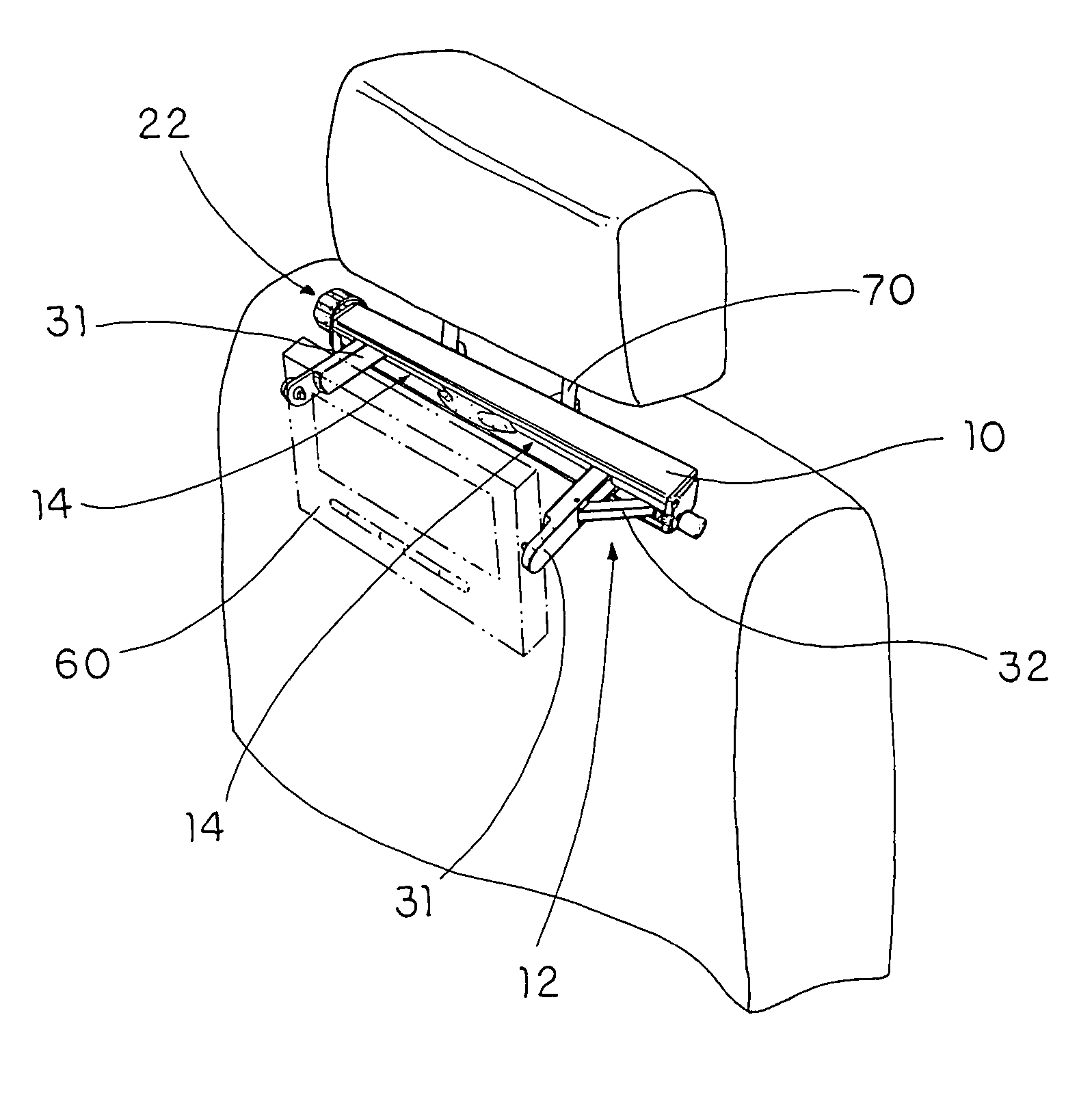
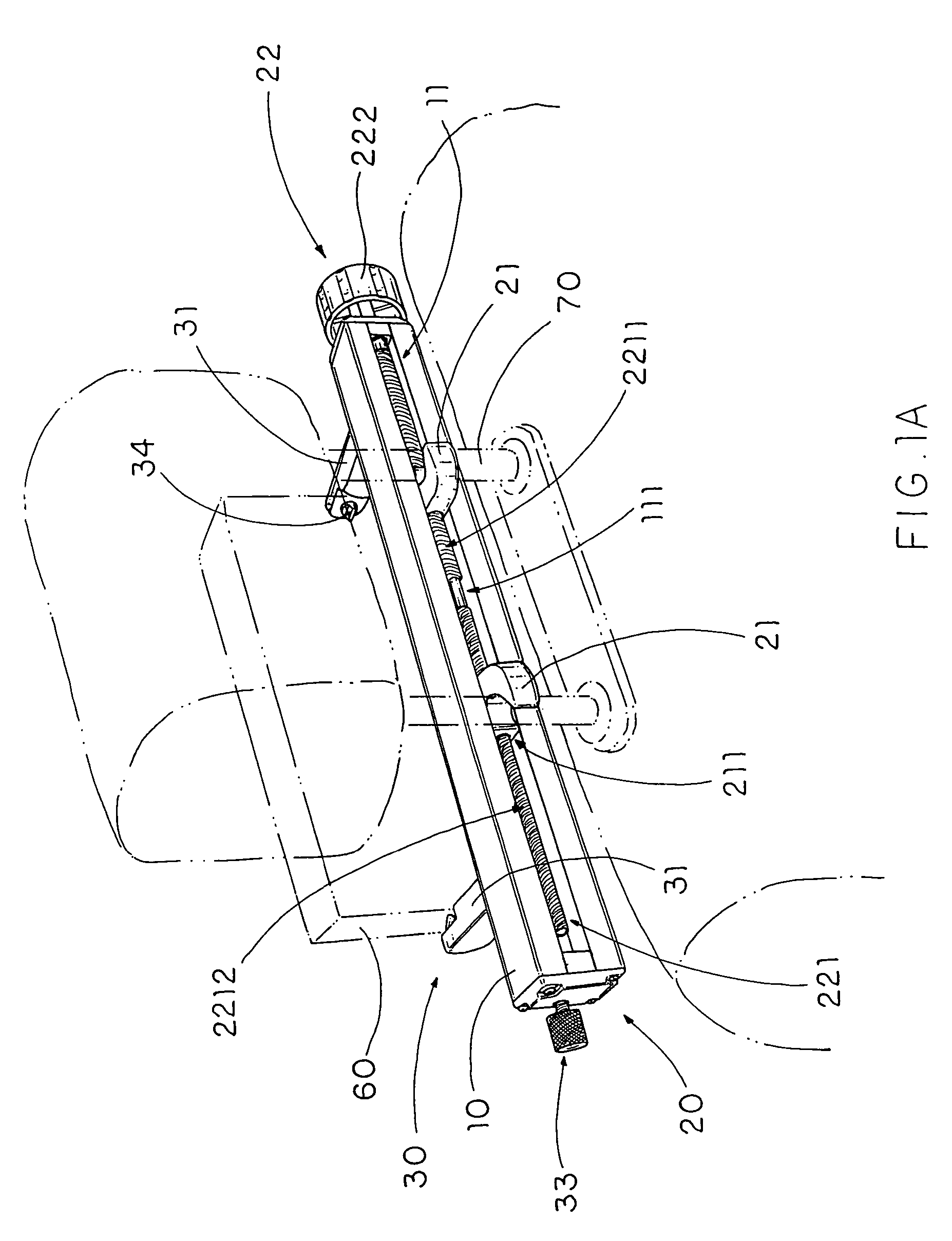
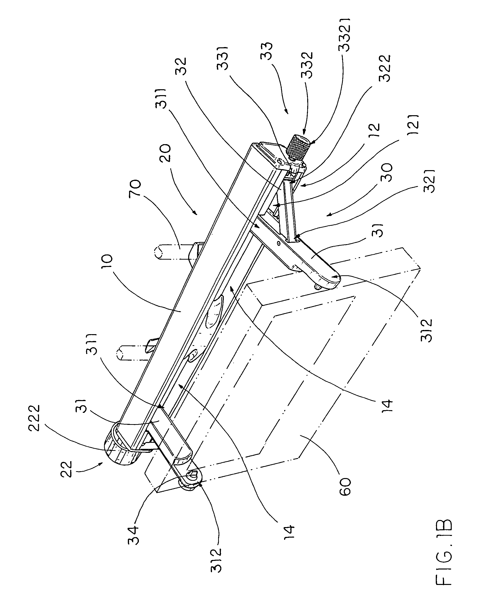
[0034]Referring to FIGS. 1A, 1B and 3 of the drawings, a portable mounting device for mounting a mobile entertainment unit 60 onto two spacedly apart supporters 70 is illustrated. The mobile entertainment unit 60, such as a DVD player or other multimedia player, is mounted by the portable mounting device on the two supporters 70, such as the two extension bars connecting between a head rest and a seat back of a vehicle seat. Therefore, the head rest is adapted to be selectively adjusted a height from the seat back according to the head size of the user.

[0035]According to the preferred embodiment, the mobile entertainment unit 60 is detachably supported at a rear side of the vehicle seat for providing optimal display of the relevant multimedia materials to a user(s) seating at the back of that vehicle seat. Accordingly, the portable mounting device comprises an elongated housing 10, a fixture mounting unit 20, and an entertainment mounting device 30.

[0036]The elongated housing 10, ha...


PUM


Abstract

A portable mounting device for mounting a mobile entertainment unit onto two spaced apart supporters includes an elongated housing, a fixture mounting unit and an entertainment mounting device. The fixture mounting unit includes two retention arms spacedly provided on the fixture mounting side of the elongated housing for detachably engaging with the supporters respectively, and an adjuster provided at the elongated housing to selectively adjust the retention distance between the retention arms. The entertainment mounting device provided on the holding side of the elongated housing for detachably holding the mobile entertainment unit in position so as to securely support the mobile entertainment unit by the supporters.

Description

BACKGROUND OF THE INVENTION[0001]1. Field of Invention[0002]The present invention relates to a mounting device, and more particularly to a portable mounting device for a mobile entertainment unit which is adapted for mounting the entertainment unit on two spaced apart supporters, such as two head support extensions of a vehicle seat.[0003]2. Description of Related Arts[0004]Mobil entertainment units, such as portable DVD players, have widely utilized for playing multimedia materials in outdoors environment. They are usually compact in size, foldable, and contain rechargeable battery so as to become a self-contained unit for providing maximum convenience to their users.[0005]One common disadvantage of those traditional mobile entertainment units is that they usually lack some sorts of supports or mounting arrangements for them to be attached on a secure structure, such as the two head support extensions of a vehicle seat, so that their users do not need to hold them manually during t...

Claims


Application Information

Patent Timeline
Patent Type & Authority Patents(United States)
IPC IPC(8): A47C7/72
CPCB60R11/0235B60R2011/0017
Inventor ZHENG, EDWARD
Owner ZHENG EDWARD
Why Eureka
Try Eureka