Laborsaving and safety lighters

a technology of safety and labor saving, which is applied in the field of electric lighters, can solve the problems of laborious operation of currently available lighters, inability to reduce the force needed to press the button difficulty in operation of currently available piezoelectric lighters, so as to improve prevent misoperation, and increase the safety of the lighter

Active Publication Date: 2008-04-29
NINGBO XINHAI INT TRADE CO LTD
View PDF7 Cites 13 Cited by
  • Summary
  • Abstract
  • Description
  • Claims
  • Application Information

AI Technical Summary

Benefits of technology

[0005]The purpose of the invention is to provide a laborsaving lighter which can improve the feeling of operation of electronic (piezoelectric) straight-log lighters so that it becomes dexterous and easy to press the lighter's button.
[0006]Another purpose of this invention is to provide a safe and laborsaving lighter which saves labor in operation and is equipped with a safety device. It can reduce the force needed to light up the lighter, and can effectively control the button's working state such that the button cannot be pressed downwards directly to improve the safety of the lighter and eliminate the aforesaid potential hazards.

Problems solved by technology

Therefore, it is laborious to operate the currently available lighters.
That's why it is generally believed that the currently available piezoelectric lighters are hard to operate and are not dexterous for lighting-up.
It is impossible to reduce the force needed to press the button of the currently available piezoelectric lighters because of their structure constraints.
Besides, the above-mentioned lighters do not have any safety assembly, and there is no restriction of downwards pressing the button.
The lighter is very likely ignited when the button is accidentally pressed in children's play or struck by a hard object accidentally, which will do harm to children or even threaten the public security.
Further more, when the button is accidentally pressed by an external force, the gas emitting valve is opens and the inflammable gas leaks.
This is a potential safety hazard, though it might not cause a flame appear.
Therefore, it is clearly prohibited in some regions and countries to manufacture and sell the lighters without a safety device.

Method used


Image

  • Laborsaving and safety lighters
  • Laborsaving and safety lighters
  • Laborsaving and safety lighters

Examples


example 1

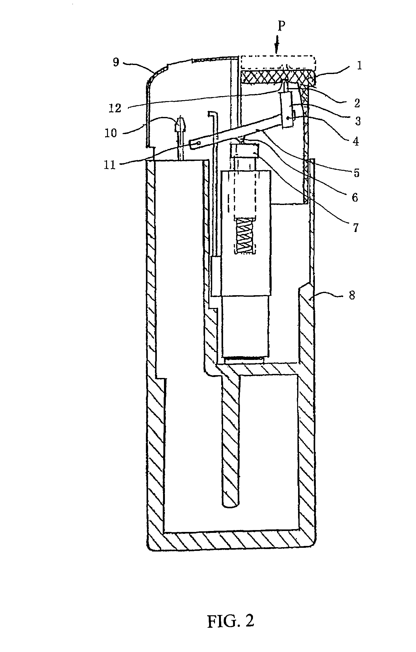
[0044]FIG. 2 and FIG. 3 illustrate a particular example of this invention. As shown in FIG. 2, all components of the lighter's force reduction device are enclosed in a casing 8. The force reduction device comprises a lever 5, and there is an active force part 4 with a force point and a fixed part 11 with a fixed point respectively on each end of lever 5, and a middle part 6 with a depressing point. The active force part 4 in an end of the lever 5 is pivotally connected to an end of a connecting rod 3 by a pin (not illustrated). The force point on the lever 5 functions as a pivot for moment transfer. There is a long and thin elongated bar 2 at the other end of the connecting rod 3, and the elongated bar can be named as an elongated bar of button-to-connecting rod.

[0045]The elongated bar 2 contacts with a concave cambered surface 12 of the button 1. The cambered surface 12 and the elongated bar of button-to-connecting rod 2 can be in spot contact or adjacent, which is designed to ensu...

example 2

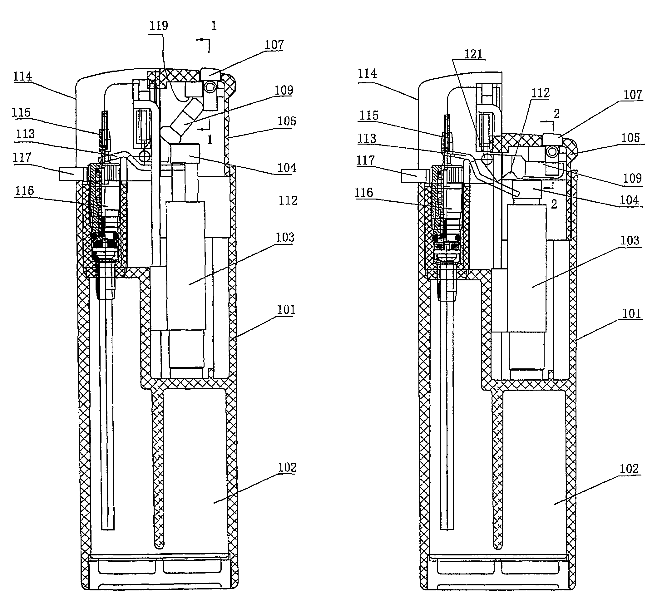
[0049]As shown in FIGS. 4-7, the example is a safe and laborsaving lighter, which is another preferred examples of the invention.

[0050]As shown in FIGS. 4-7, the lighter comprises a casing 101, a fuel tank 102 in the casing 101, a piezoelectric assembly and a gas emitting assembly, as well as windshield 114 over the gas emitting assembly. The casing 101 serves as the fuel tank wall. The piezoelectric assembly comprises a piezoelectrics element 103, a piezoelectric push rod 104 and a button 105. The gas emitting assembly consists of a gas emitting nozzle 115, a gas emitting valve 116 and an adjustment ring 117. There is a pry board 113 between the gas emitting assembly and the piezoelectric assembly for linkage of them. In the end face of button 105, there is a vertical slot opening 106 which receives an L-shaped safety piece 107. There is a return spring 120 between the sidewall of the safety piece 107 and the button 105. There is a rock arm 109 above the pry board 113 to the safety...

example 3

[0056]See also FIG. 8. Example 3 is the same as example 2 but the rock arm. Rock arm 109′ in this example adopts the structure as shown in FIG. 8. Compared with the rock arm 109 in example 2, the rock arm 109′ in this example has only one protrusion 110′ on its right side. In the normal state, the lower part 107a of the safety piece 107 rests on protrusion 110′ of rock arm 109′. The other structure and operation principle in this example are the same as those in example 2.


PUM


Abstract

This invention relates to a laborsaving lighter, and more particularly relates to a laborsaving and safe lighter, which includes a casing (101), and a piezoelectric assembly and a gas emitting assembly disposed in the casing. The piezoelectric assembly includes a piezoelectric push rod (104) and a button (105). A vertical slot opening (106) is formed in the end face of the button (105), and a safety piece (107) is disposed in the slot opening (106). There is a rock arm (109) between the gas emitting assembly and the safety piece (107). In the lighter's non-operative state, the upper end of the rock arm (109) rests against the lower part (107a) of the safety piece (107). The middle part of the rock arm is contacted with the piezoelectric push rod (104), and the lower end of the rock arm is connected pivotally to the inner surface of the casing (101). According to the principle of lever, the present invention is laborsaving as well as safety. The action of depressing the button is laborsaving and convenient, and the travel path of the button is effectively controlled. It avoids the phenomena of igniting the inflammable gas or gas leakage with by directly depressing the button pressed downward directly or gas leakage due to the button being accidentally pressed, and improves the lighter's safety by the prevention of misoperation and the increase of operation difficulties for children.

Description

TECHNICAL FIELD[0001]This invention relates to an electronic lighter and more particularly to a force reduction device of a lighter; and this invention also relates to a laborsaving lighter with a safety device disposed on the lighter's button.BACKGROUND OF THE INVENTION[0002]The existing electronic lighters are a kind of electronic ignition device that uses an inflammable gas such as butane or natural gas as fuel. Such a lighter includes a casing, a fuel tank in the casing, a piezoelectric assembly, a gas emitting assembly and a windshield over the gas emitting assembly. The gas emitting assembly includes a gas emitting nozzle, a gas emitting valve and a flame-adjusting ring. The piezoelectric assembly includes a piezoelectric element, a piezoelectric push rod and a button. A linkage pry board is disposed between the gas emitting assembly and the piezoelectric assembly. The operation principle is as follows: by pressing downwards the button with your thumb, the button or a connecti...

Claims


Application Information

Patent Timeline
Patent Type & Authority Patents(United States)
IPC IPC(8): F23Q2/08F23D11/36F23Q2/28F23Q2/16F23Q2/34
CPCF23Q2/287F23Q2/34
Inventor HUANG, XINHUAWANG, ZHENGRONG
Owner NINGBO XINHAI INT TRADE CO LTD
Why Eureka
Try Eureka