Co-simulation interface

a technology of co-simulation interface and hdl components, which is applied in the direction of cad circuit design, program control, instruments, etc., can solve the problem of limited simulation options availabl

Active Publication Date: 2008-04-29
XILINX INC
View PDF8 Cites 12 Cited by
  • Summary
  • Abstract
  • Description
  • Claims
  • Application Information

AI Technical Summary

Problems solved by technology

However, even with the varied types of co-simulation engines and different high-level modeling systems, the available simulation options may be limited by a lack of infrastructure to support communication between the high-level and low-level simulation components.

Method used


Image

  • Co-simulation interface
  • Co-simulation interface
  • Co-simulation interface

Examples


Embodiment Construction

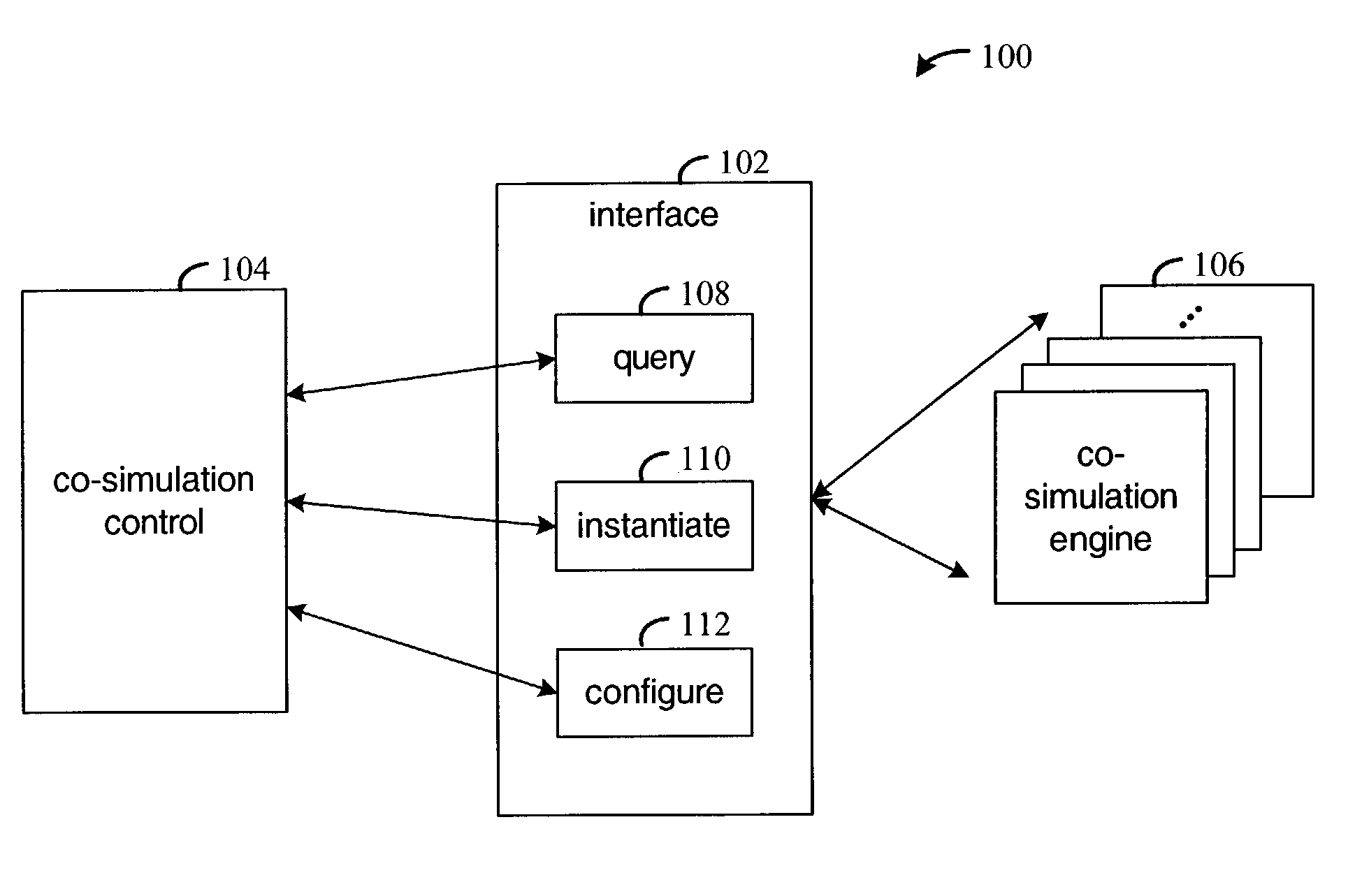
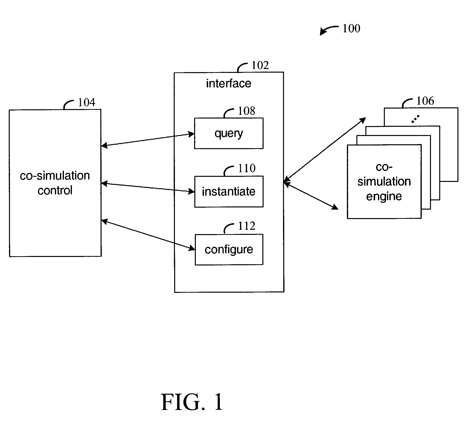
[0016]The framework that is provided in various embodiments of the invention provides a common interface across multiple types of software-based and hardware-based co-simulation engines. From the perspective of an HLMS, the co-simulation engines operate similarly. Representative functions provided by the interface include querying co-simulation engines for capabilities, instantiating instances of co-simulation engines, and configuring the co-simulation engines with data required for co-simulation and tailored for each engine.

[0017]FIG. 1 is a functional block diagram of an arrangement 100 for co-simulation of an electronic circuit design in accordance with various embodiments of the invention. The elements of interface 102 support interaction between a co-simulation control element 104 and a set of co-simulation engines 106. The co-simulation control element 104 controls the overall simulation. For example, if a design includes both high-level and HDL level components, the co-simula...


PUM


Abstract

Method and apparatus for interfacing between a high-level modeling system and a hardware description language (HDL) co-simulation engine. A plurality of HDL co-simulation engine libraries are queried as to the capabilities of the engines. A co-simulation engine is selected based on the capabilities, and an instance of the engine is created. The selected co-simulation engine is configured, input logic vectors are provided to the selected HDL co-simulation engine, and the co-simulation engine is executed accordingly.

Description

FIELD OF THE INVENTION[0001]The present invention generally relates to co-simulating HDL components in a high-level modeling system.BACKGROUND[0002]A high level modeling system (HLMS) is a software tool in which electronic designs can be described, simulated, and translated by machine into a design realization. An HLMS provides a higher level of abstraction for describing an electronic circuit than a hardware description language (HDL) simulation environment such as the ModelSim environment from the Model Technology company. An HLMS generally provides a mathematical representation of signals as compared to standard logic vectors in a hardware description language (HDL). It is desirable for the high-level abstractions to be precisely correlated with the ultimate implementation representation, both in simulation semantics and in implementation. The Xilinx System Generator tool for DSP and the MathWorks' Simulink and MATLAB environments are example HLMS's in which such capabilities are...

Claims


Application Information

Patent Timeline
Patent Type & Authority Patents(United States)
IPC IPC(8): G06F9/455G06F17/00G06F17/50G06F9/00G06F9/06G06F9/44G01R31/28G01R35/00G06F11/00
CPCG06F17/5022G06F2217/86G06F30/33G06F2117/08
Inventor MILNE, ROGER B.BALLAGH, JONATHAN B.STROOMER, JEFFREY D.
Owner XILINX INC
Why Eureka
Try Eureka