Automating a microarchitecture design exploration environment

a microarchitecture and design exploration technology, applied in the field of integrated circuit design, can solve the problems of reducing the ability of designers to evaluate their modules without other modules, and not being able to fully simulate or synthesize the overall design

Inactive Publication Date: 2016-08-02
IBM CORP
View PDF14 Cites 5 Cited by
  • Summary
  • Abstract
  • Description
  • Claims
  • Application Information

AI Technical Summary

Benefits of technology

[0009]An exemplary embodiment is a computing system, comprising: one or more memories comprising computer-readable code; and one or more processors, which in response to execution of the computer readable code cause the computing system to perform the following: running an environment for designing operation of circuitry, wherein running the environment comprises performing at least the following for providing simulations and evaluations of one or more user-defined modules of circuitry comprising one or more pipeline stages in a pipeline: automatically generating a model of the pipeline by using a pipeline block diagram, where the model is generated in a high-level modeling language able to perform simulations of circuitry with the pipeline; automatically generating an interface between the one or more user-defined modules and the generated model of the pipeline, the interface comprising a set of access methods to the pipeline; and performing evaluation of the one or more user-defined modules using the automatically generated model of the pipeline and the automatically generated interfac...

Problems solved by technology

Modules may be abstract so as to capture partial logic or miss out low-level details, and thus not ready for synthesis yet.
However, traditional design environments do not support such parallelized design productivity, thereby reducing the ability for the designers to evaluate their modules without other modules.
This is particularly true for complex, pipelined logic, such as processor desig...

Method used


Image

  • Automating a microarchitecture design exploration environment
  • Automating a microarchitecture design exploration environment
  • Automating a microarchitecture design exploration environment

Examples


example 1

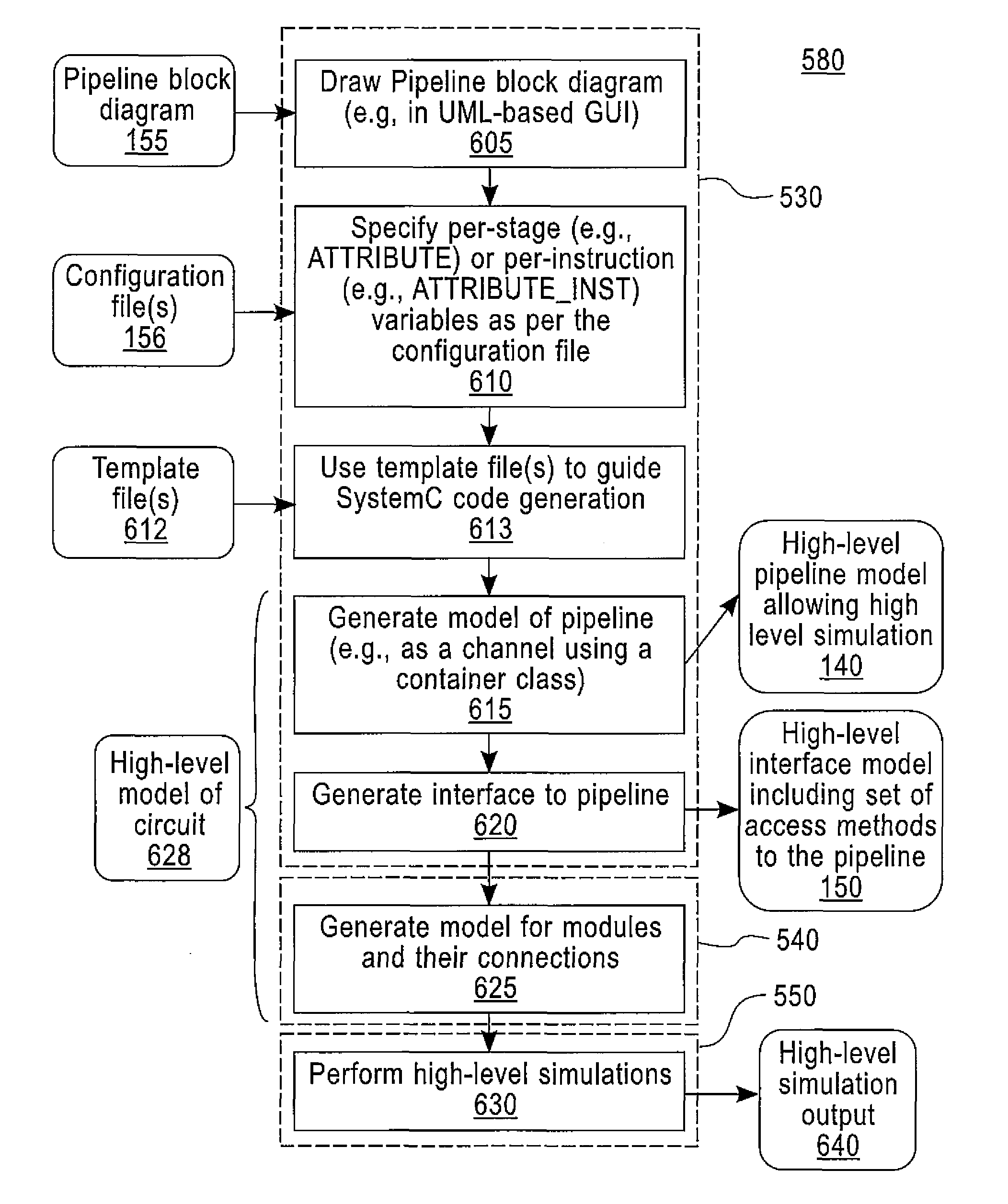
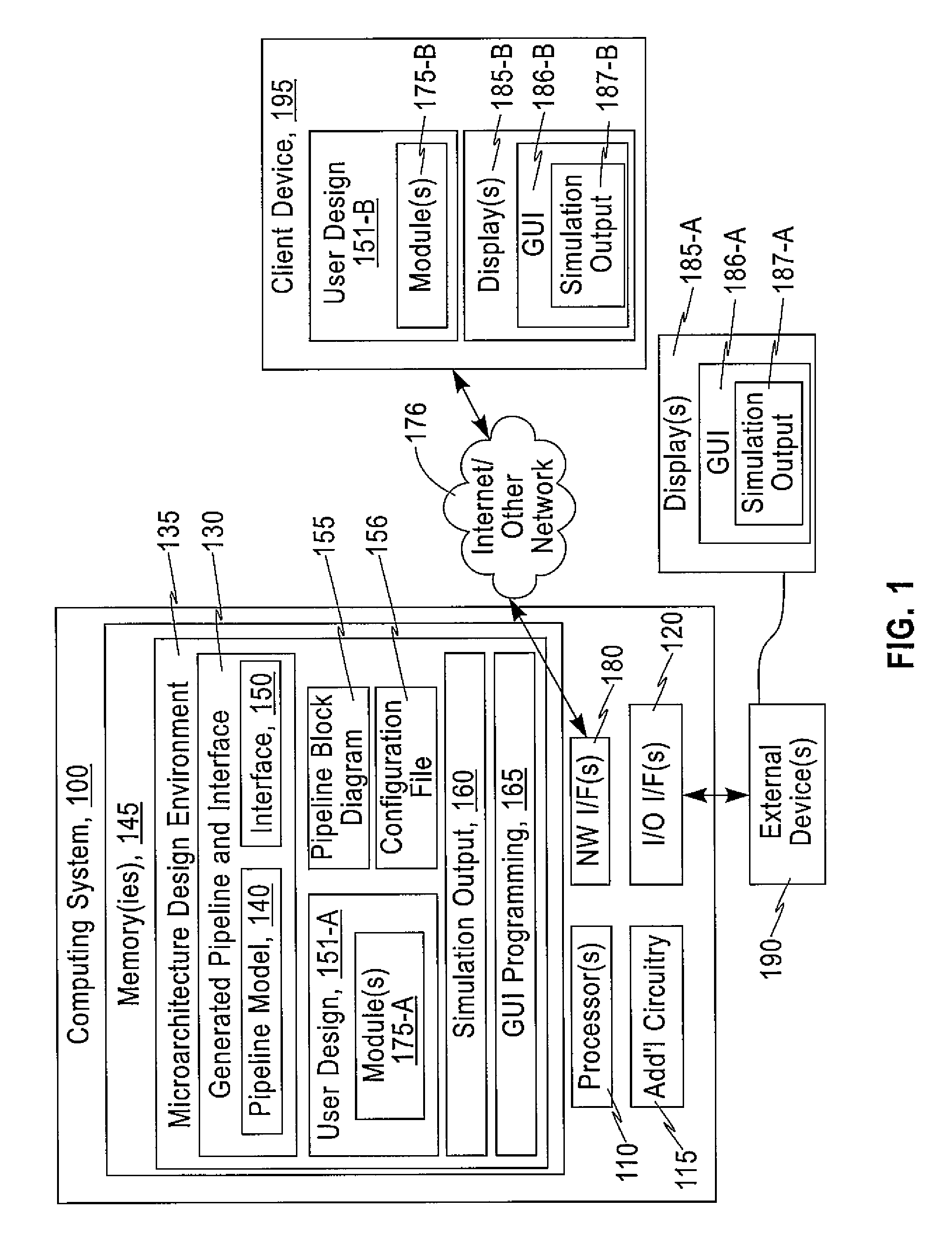
[0071]A method comprising: in a computing system running an environment for designing operation of circuitry, performing at least the following for providing simulations and evaluations of one or more user-defined modules of circuitry comprising one or more pipeline stages in a pipeline: automatically generating a model of the pipeline by using a pipeline block diagram, where the model is generated in a high-level modeling language able to perform simulations of circuitry with the pipeline; automatically generating an interface between the one or more user-defined modules and the generated model of the pipeline, the interface comprising a set of access methods to the pipeline; and performing evaluation of the one or more user-defined modules using the automatically generated model of the pipeline and the automatically generated interface.

example 2

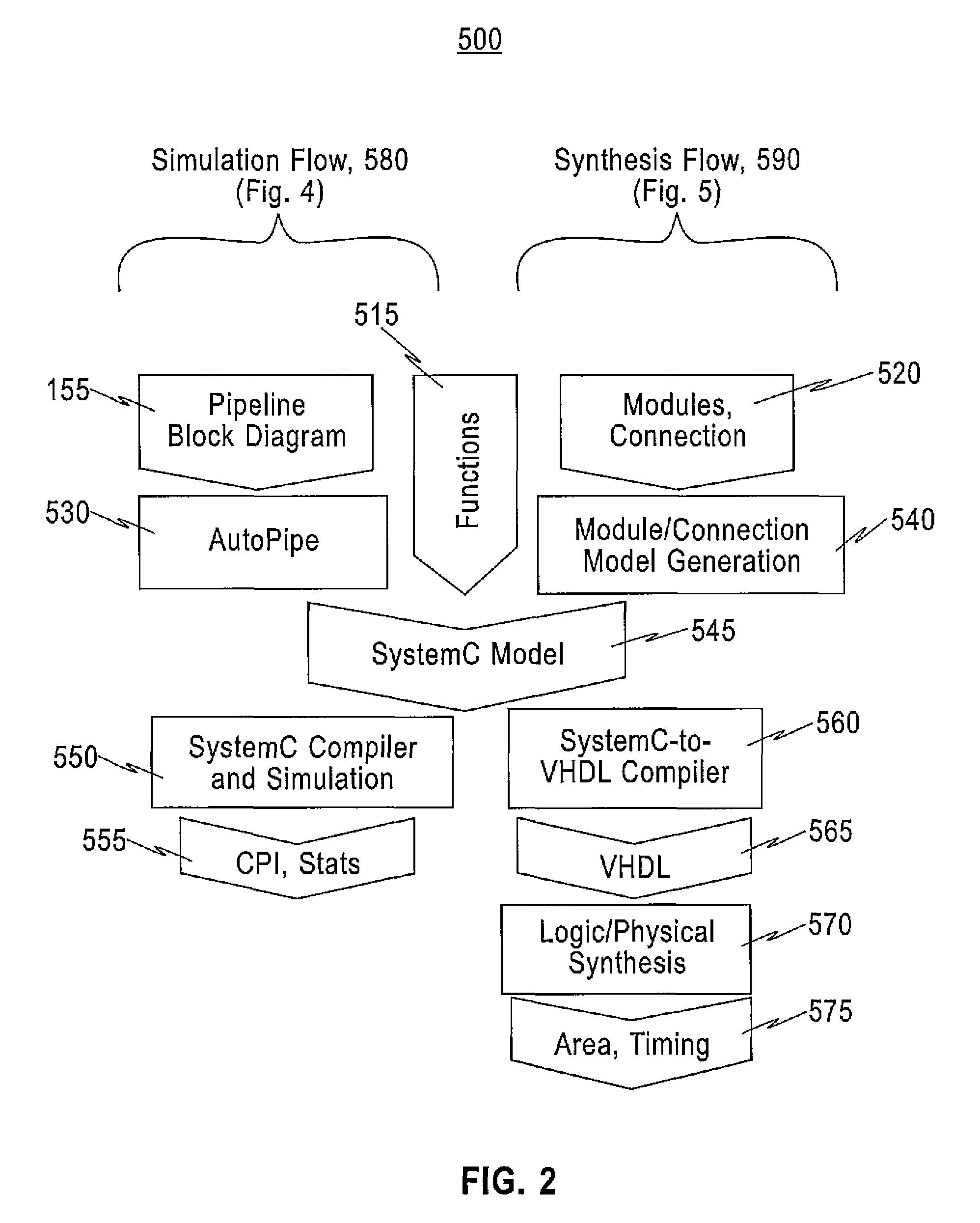
[0072]The method of Example 1, wherein the automatically generating a model and the automatically generating an interface are for a simulation flow supported by the environment, and wherein in response to a request to create synthesized versions of the one or more user-defined modules the environment performs a synthesis flow wherein: automatically generating an interface further comprises synthesizing the interface at least by converting the set of access methods to the pipeline to a set of ports in a hardware description language; and performing simulations further comprises performing simulations on the one or more user-defined modules with workloads using the automatically generated model of the pipeline and the automatically generated model of the interface to determine one or more design evaluation metrics of the one or more user-defined modules.

example 3

[0073]The method of Example 2, wherein the one or more design evaluation metrics comprise one or both of at least one quality of hardware metric or at least one performance metric.


PUM


Abstract

In a computing system running an environment for designing operation of circuitry, at least the following are performed for providing simulations and evaluations of one or more user-defined modules of circuitry including one or more pipeline stages in a pipeline. A model of the pipeline is automatically generated by using a pipeline block diagram, where the model is generated in a high-level modeling language able to perform simulations of circuitry with the pipeline. An interface is automatically generated between the one or more user-defined modules and the generated model of the pipeline, the interface including a set of access methods to the pipeline. Evaluation is performed of the one or more user-defined modules using the automatically generated model of the pipeline and the automatically generated interface. Methods, apparatus, and computer program products are disclosed.

Description

CROSS-REFERENCE TO RELATED APPLICATIONS[0001]This application is a continuation of U.S. patent application Ser. No. 14 / 725,122, filed on May 29, 2015, the disclosure of which is hereby incorporated by reference in its entirety.BACKGROUND[0002]This invention relates generally to design of integrated circuits such as processors and, more specifically, relates to environments in which such design is carried out.[0003]Much process of modern micro architecture design for integrated circuits such as processors has been—to a large degree—automated. Individual or teams of designers develop modules that perform sets of functions. Each module forms one part of the design. These modules are implemented according to the specification of logic, simulated for functional correctness and performance evaluation, and finally synthesized into integrated circuits in a design environment. Modules may also be called macros or blocks.[0004]The modules can be implemented in a hardware description language ...

Claims


Application Information

Patent Timeline
IPC IPC(8): G06F17/50
CPCG06F17/5009G06F17/505G06F2115/10G06F30/33G06F30/327G06F30/367G06F30/20
Inventor CHO, MINSIKKONIGSBURG, BRIAN R.NAIR, INDIRAREN, HAOXINGSHIN, JEONGHEE
Owner IBM CORP
Why Eureka
Try Eureka