
Floor tool

a technology for floor tools and hoses, which is applied in the direction of mechanical suction control, suction nozzles, suction hoses, etc., can solve the problems of the sole plate 150/b> of the tool to lift off the floor surface, and the detrimental effect of the floor tool pick-up performance, so as to increase the pick-up performance of the tool

Inactive Publication Date: 2008-05-06
DYSON TECH LTD
View PDF16 Cites 8 Cited by
  • Summary
  • Abstract
  • Description
  • Claims
  • Application Information

AI Technical Summary

Benefits of technology

[0007]This has the advantage that the floor tool is less prone to lifting off of a floor surface as a user manipulates the tool. We have found that this improved contact with the floor surface can increase the pick-up performance of the tool.

Problems solved by technology

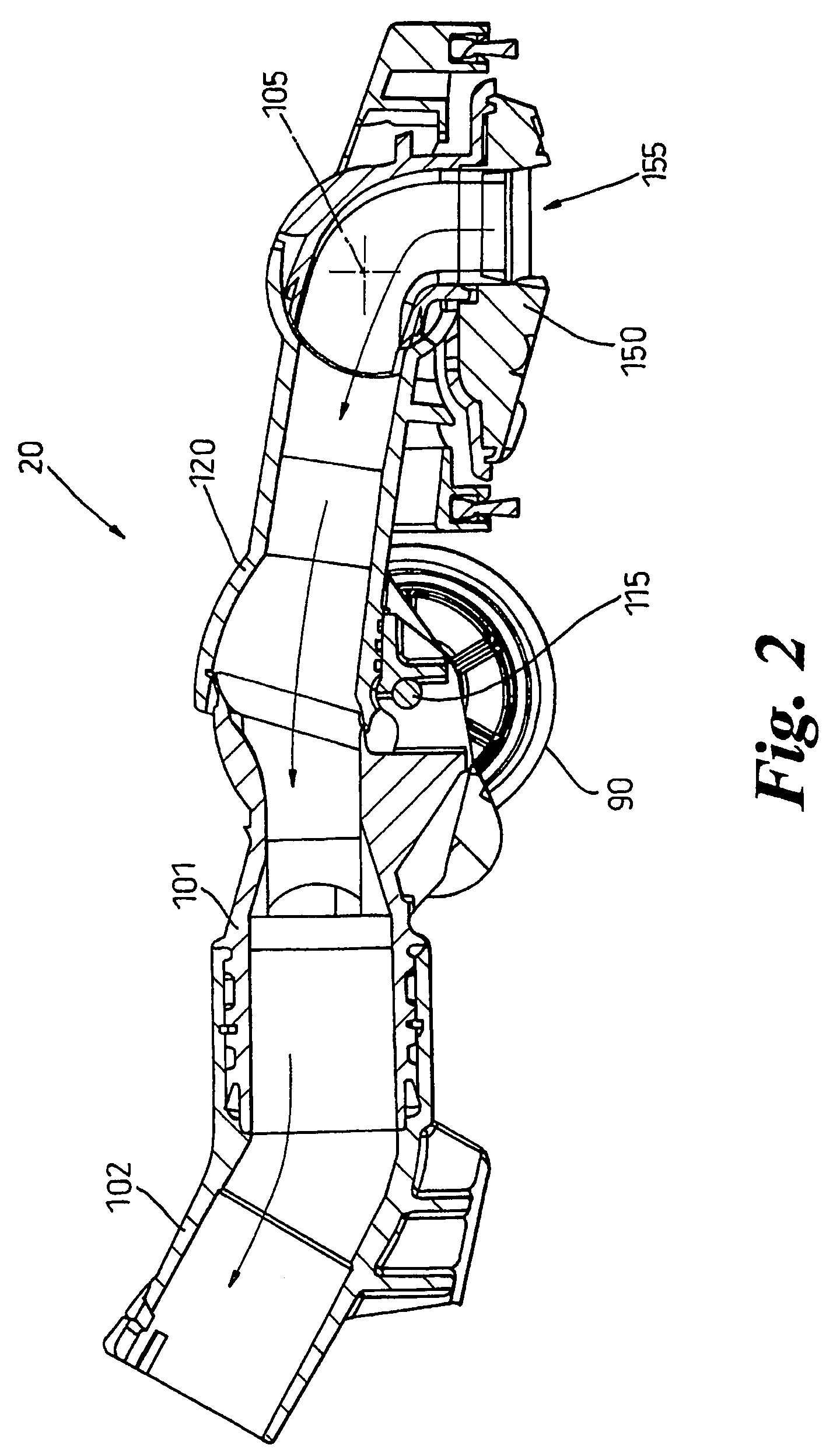
However, it has been found that the manner in which some users operate the wand can cause the sole plate 150 of the tool 20 to lift off of the floor surface.
This has a detrimental effect on the pick-up performance of the floor tool 20.

Method used


Image

  • Floor tool
  • Floor tool
  • Floor tool

Examples


Embodiment Construction

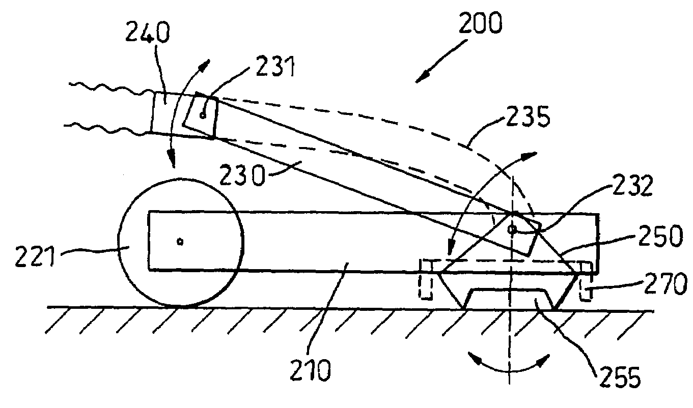
[0031]FIG. 3 shows, in simplified form, the components of a floor tool in accordance with a first embodiment of the invention. The main components of the tool 200 are a main chassis 210, a sole plate 250, a wand connector 240 for connecting to a wand or hose of a vacuum cleaner, a connecting arm 230 which connects the chassis 210 to the wand connector 240 and a hose 235 for carrying airflow from the sole plate 250 to the wand connector 240. The sole plate defines an air inlet 255 which, in use, faces the floor surface and extends transversely across the full width of the tool. The chassis 210 is provided with wheels 221 to allow it to move across a floor surface. The wand connector 240 is dimensioned so as to mate with a wand (i.e. a pipe or a set of telescopic pipes) of a vacuum cleaner. The wand connector 240 is connected to the chassis 210 by a connecting arm 230. A first end of the connecting arm 230 is pivotally connected to the wand connector 240 by a joint 231. The other end ...


PUM


Abstract

A floor tool for use in vacuum cleaning floor surfaces includes a sole plate for engaging with a floor surface, a supporting body for the sole plate having means such as wheels or rollers for allowing the body to ride along the floor surface and an outlet conduit for coupling to a wand of a vacuum cleaner. The outlet conduit is mounted to the support platform by a connecting arm, a first end of the connecting arm being pivotally connected to the outlet conduit about a first axis and the second end of the connecting arm being pivotally connected to the supporting body about a second axis. The first and second axes are substantially parallel to one another. Fluid flow from the sole plate can be carried by a flexible hose or by the connecting arm itself.

Description

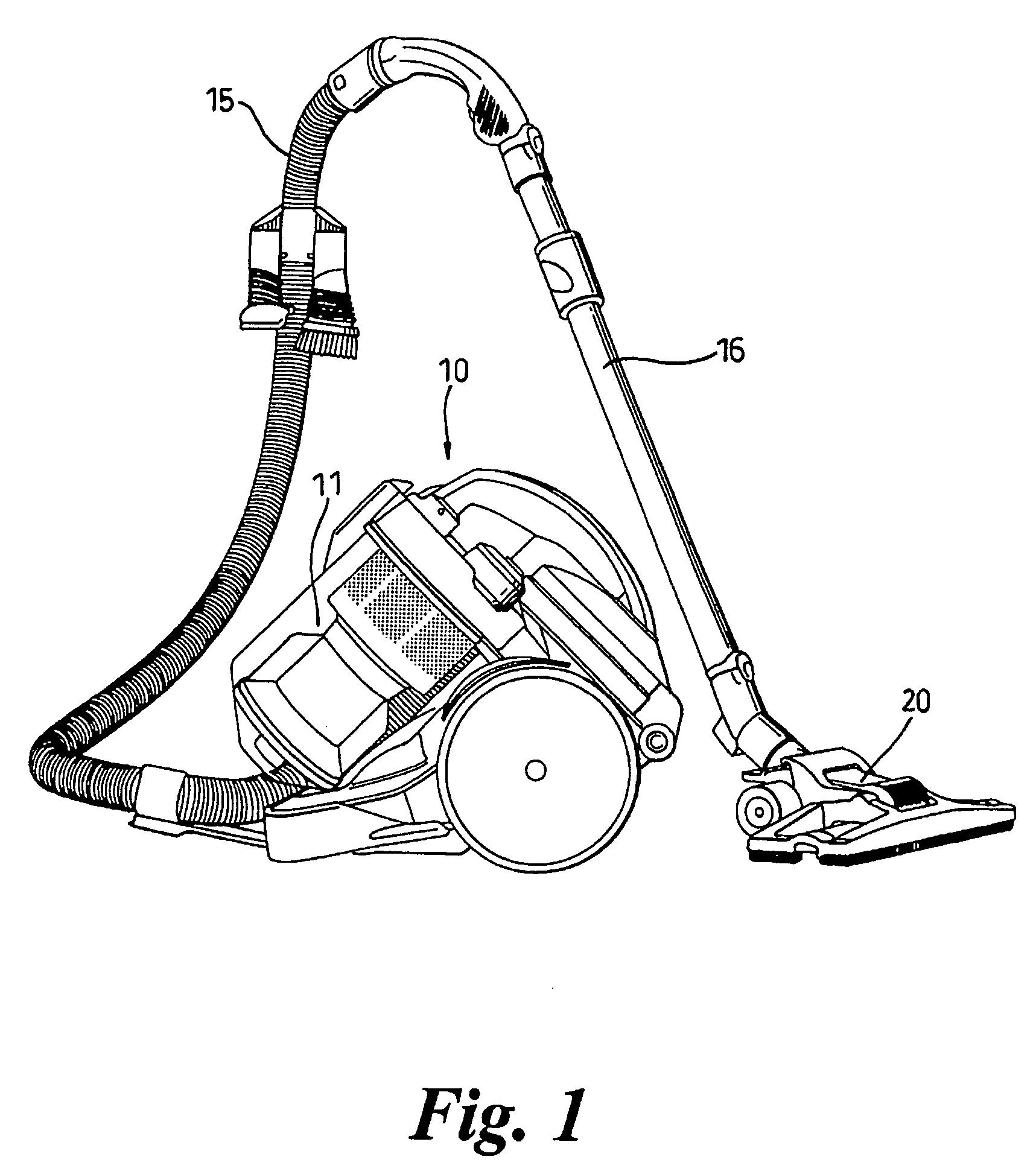
REFERENCE TO RELATED APPLICATIONS[0001]This application is the national stage under 35 USC 271 of International Application No. PCT / GB02 / 04834, filed Oct. 25, 2002, which claims the priority of United Kingdom Application Nos. 0126494.4 and 020692.3, filed Nov. 3, 2001, and Apr. 27, 2002, respectively, the entire contents of which are incorporated herein by reference.FIELD OF THE INVENTION[0002]This invention relates to a floor tool for use with a vacuum cleaner.BACKGROUND OF THE INVENTION[0003]Cylinder or canister vacuum cleaners, as shown in FIG. 1, generally comprise a main body 10 which contains separating apparatus 11 such as a cyclonic separator or a bag for separating dirt and dust from an incoming dirty airflow. The dirty airflow is introduced to the main body 10 via a hose 15 and wand 16 assembly which is connected to the main body 10. The main body 10 of the cleaner is dragged along by the hose as a user moves around a room. A cleaning tool is attached to the remote end of ...

Claims


Application Information

Patent Timeline
Patent Type & Authority Patents(United States)
IPC IPC(8): A47L9/02A47L9/00A47L9/06A47L9/24
CPCA47L9/0072A47L9/02A47L9/06A47L9/0613A47L9/0653A47L9/0666A47L9/242
Inventor BAGWELL, MARTIN PAULANDERSON, ALASTAIR GORDON
Owner DYSON TECH LTD
Learn More