Optical pickup device and its manufacturing method

Inactive Publication Date: 2004-05-20
SHARP KK
View PDF1 Cites 5 Cited by
  • Summary
  • Abstract
  • Description
  • Claims
  • Application Information

AI Technical Summary

Problems solved by technology

However, in such a conventional optical pickup device, since the housing 100 is formed of a synthetic resin composition such as a silicon resin or an acrylic resin so as to have a thick wall for increasing the strength of the whole device, the housing is heavy in weight.
Also, though a high performance of the optical pickup device can be ensured in

Method used


Image

  • Optical pickup device and its manufacturing method
  • Optical pickup device and its manufacturing method
  • Optical pickup device and its manufacturing method

Examples


Embodiment Construction

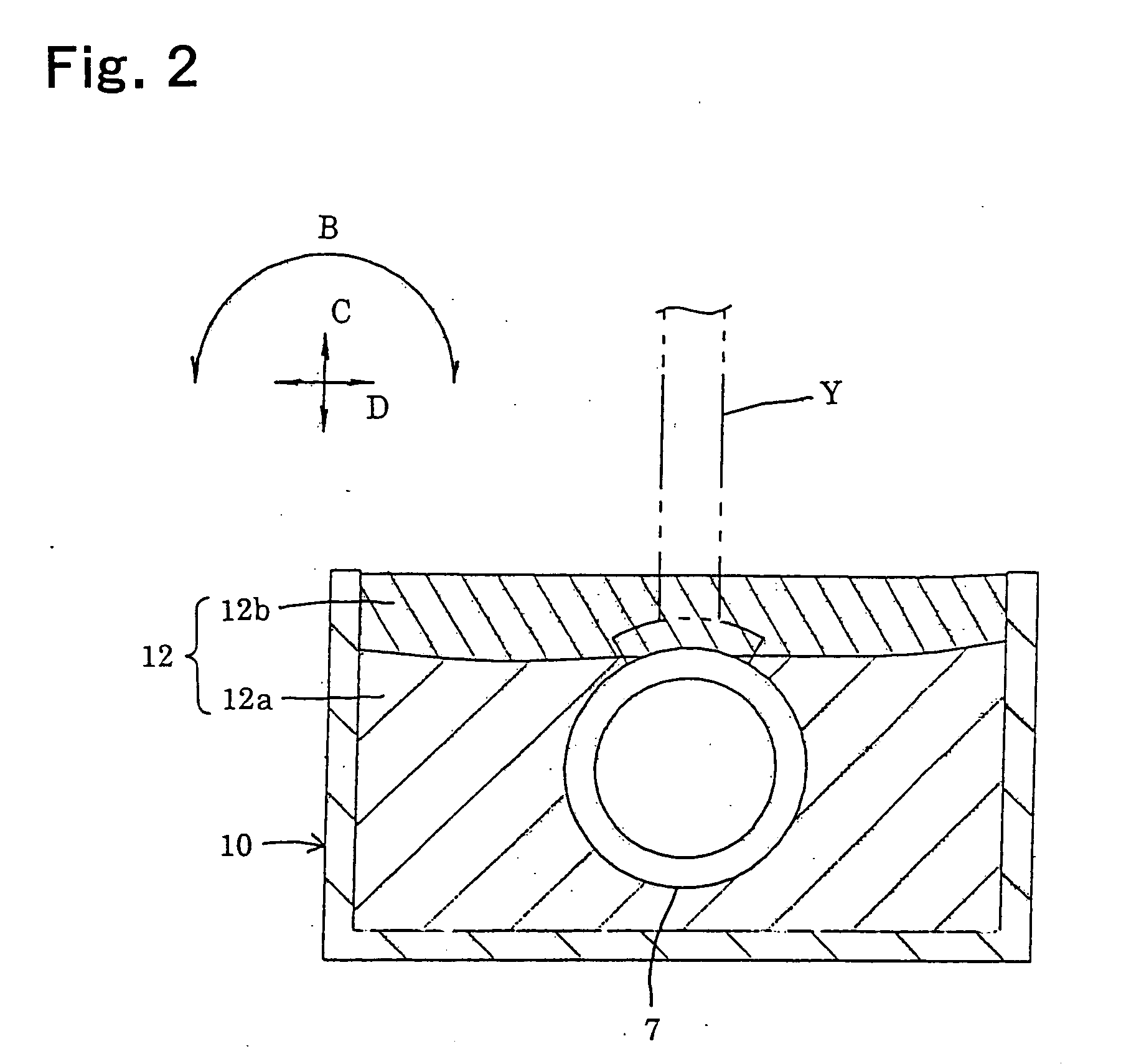
[0067] 1. In the above-mentioned embodiment, the lightproof resin composition is injected into the recess 11 and then cured to form the lightproof resin portion 12b. However, a lightproof film may be attached to an upper surface of the transparent resin portion 12a instead of injecting the lightproof resin composition.

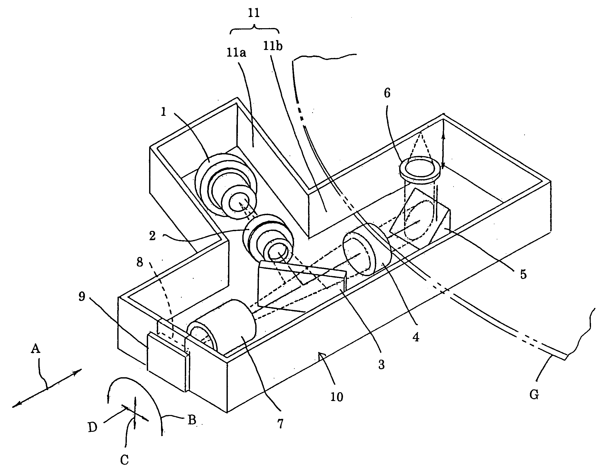
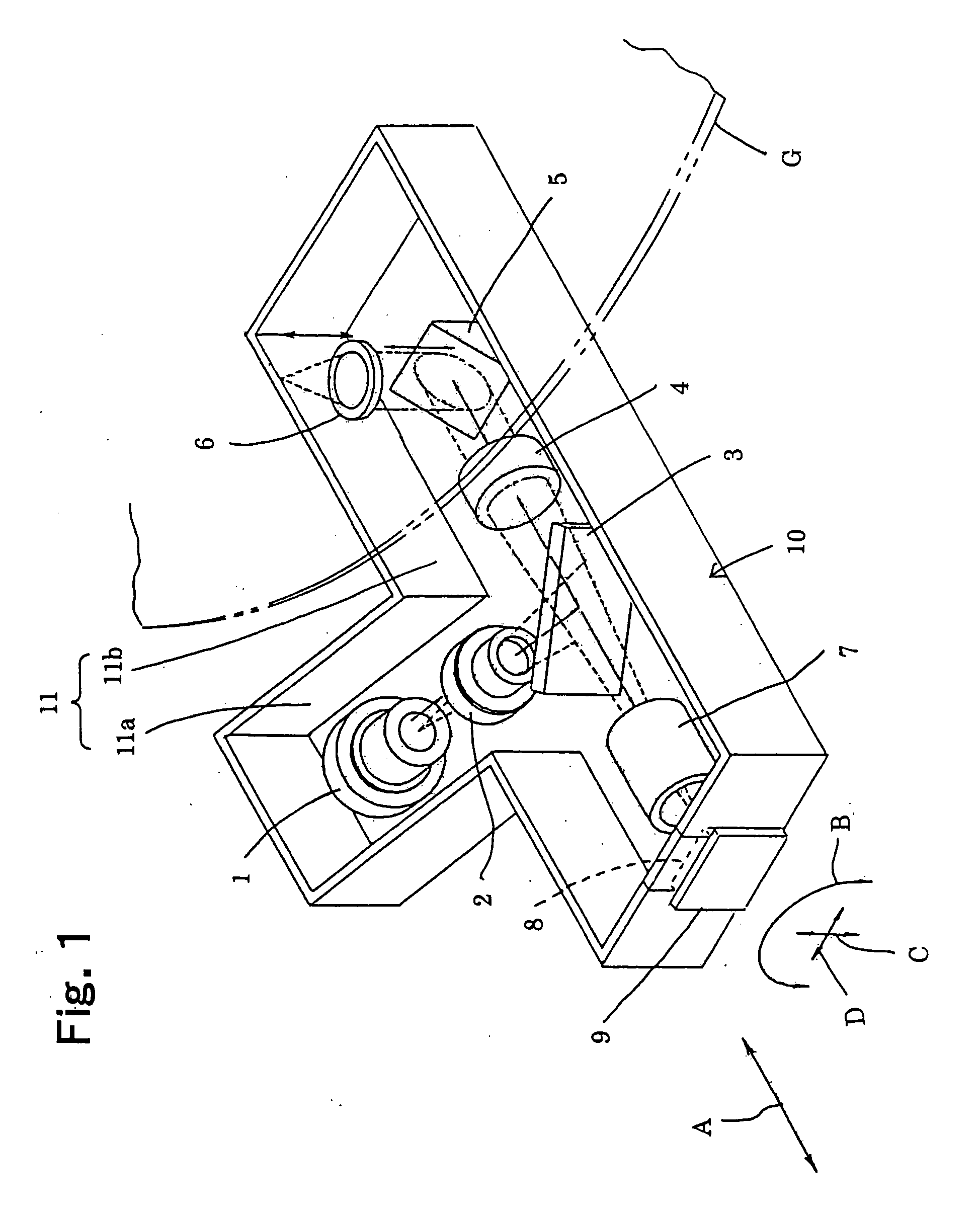
[0068] 2. In the present invention, a conventional type of housing having a thick wall (see FIGS. 3 and 4) may be used and the optical components placed in a recess of the housing may be covered with the resin member.

[0069] According to the present invention, it is possible to obtain an optical pickup device with a high reliability which can achieve high strength and reduce weight, and which can maintain an initially high pickup performance by preventing the entry of foreign matters into the optical path owing to a dustproof structure.


PUM

PropertyMeasurementUnit
Transparencyaaaaaaaaaa

Abstract

An optical pickup device includes a housing having an upper-open recess, a plurality of optical components mounted at their predetermined positions in the recess of the housing, and a resin member capable of transmitting laser light, wherein the resin member is provided for covering the optical components and fixing them at their predetermined positions in the recess.

Description

[0001] This application is related to Japanese Patent Application No. 2002-330956 filed on Nov. 14, 2002, whose priority is claimed under 35 USC .sctn. 119, the disclosure of which is incorporated by reference in its entirety.[0002] 1. Field of the Invention[0003] The present invention relates to an optical pickup device, more particularly to an optical pickup device capable of any of reproducing information from, erasing information from and recording information to an information recording medium such as an optical disc, a magneto-optical disk or the like.[0004] 2. Description of Related Art[0005] FIG. 3 is a schematic block diagram illustrating a conventional optical pickup device of this kind and FIG. 4 is an elevational view in section illustrating the conventional optical pickup device. In FIG. 3, dotted lines show portions of a travel path of laser light (an optical path), arrows near some of the dotted lines represent a travel direction of laser light and the arrow A represe...

Claims


Application Information

Patent Timeline
IPC IPC(8): G11B7/08B29C39/02B29C39/10B29C45/14B29C45/16G11B7/12G11B7/22
CPCB29C39/023B29C39/10B29C45/14467B29C45/1671B29K2063/00G11B7/22B29K2995/0025B29K2995/0026B29L2011/00B29L2017/00G11B7/12B29K2105/0032
Inventor MIYASHIGE, HIROAKI
Owner SHARP KK
Why Eureka
Try Eureka