Articulated arm for awnings, with improved elastic effect

a technology of elastic effect and articulation arm, which is applied in the direction of sunshades, domestic objects, building scaffolds, etc., can solve the problems of insufficient elastic energy accumulated in increase the rotational torque provided by the lengthening of the elastic traction element, etc., to achieve the effect of increasing the said torque, improving the elastic effect, and increasing the tension

Inactive Publication Date: 2008-05-06
LLAZA
View PDF13 Cites 27 Cited by
  • Summary
  • Abstract
  • Description
  • Claims
  • Application Information

AI Technical Summary

Benefits of technology

[0007]This invention contributes to resolving the previous need by providing an articulated awning arm, with improved elastic effect, which as usual, consists of an arm and a forearm that are joined together by respective articulation configurations located at adjacent ends of the same, which enables them to be changed between the open and closed positions. Inside the said arm is a flexible tie bar with a first end linked to at least one elastic traction element secured to a fixed point on the arm and a second end fixed to the cited articulation configuration at the said end of the forearm. The anchor point for the flexible tie bar and the elastic traction element is such that, in consequence of a relative movement between the arm and forearm on moving from the said open position to the said closed position, a lengthening of the said elastic elements under traction is produced, together with the resulting tension in the said flexible tie bar which generates a torque that tends to push the arm towards the open position. One characteristic of the awning arm of this invention is that it includes at least one elastic compression element located between a stop on the flexible tie bar and a support joined to the said end of the arm in order to produce as a consequence of the said relative movement between the arm and forearm on moving from the said open position to the said closed position, a shortening of the said elastic elements under compression is produced which is added to the cited flexible tie bar tension and contributes to increase the said torque that tends towards the open position.
[0008]Preferably, when the arm and forearm are in the open position, the elastic traction element exerts an initial traction tension having a predetermined value, while the elastic compression element exerts an initial zero or negligible value of compression tension. Because the arm and forearm are open they are in minimum positions of inclination with respect to the line of application of canvas tension, the initial traction tension of the elastic traction element is sufficient to maintain the canvas tense, and when the arm and forearm commence to move from the open position to closed, the elastic compression element comes into operation and increases its tension, which is added to that of the elastic traction element, and when the arm and forearm are completely closed, the elastic energy accumulated in both elastic elements is sufficient to push the canvas to an open position when the same is unwound. This arrangement allows the selection of the elastic elements under traction and compression so that they provide an increase in tension in the flexible tie bar in accordance with a predetermined progression as the arm and forearm move from the open position to the closed.

Problems solved by technology

One inconvenience of this type of awning arm is that the increase in rotational torque provided by the lengthening of the elastic traction element as the arm and forearm move from an open position to a closed one turns out to be insufficient with respect to the increase in resisting torque generated by the tension in the awning at the end of the forearm, taking into account that the arm and forearm adopt ever-increasingly inclined positions with respect to the line of application of the tension in the awning as they close.
When the awning canvas is completely wound onto the roll-up bar and the arm is fully folded, the elastic energy accumulated in the elastic traction element may be insufficient to push the loading bar towards an open position as the canvas is unwound.

Method used


Image

  • Articulated arm for awnings, with improved elastic effect
  • Articulated arm for awnings, with improved elastic effect

Examples


Embodiment Construction

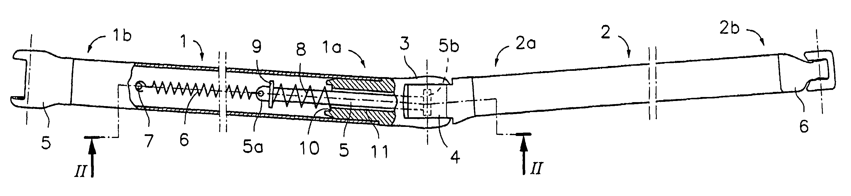
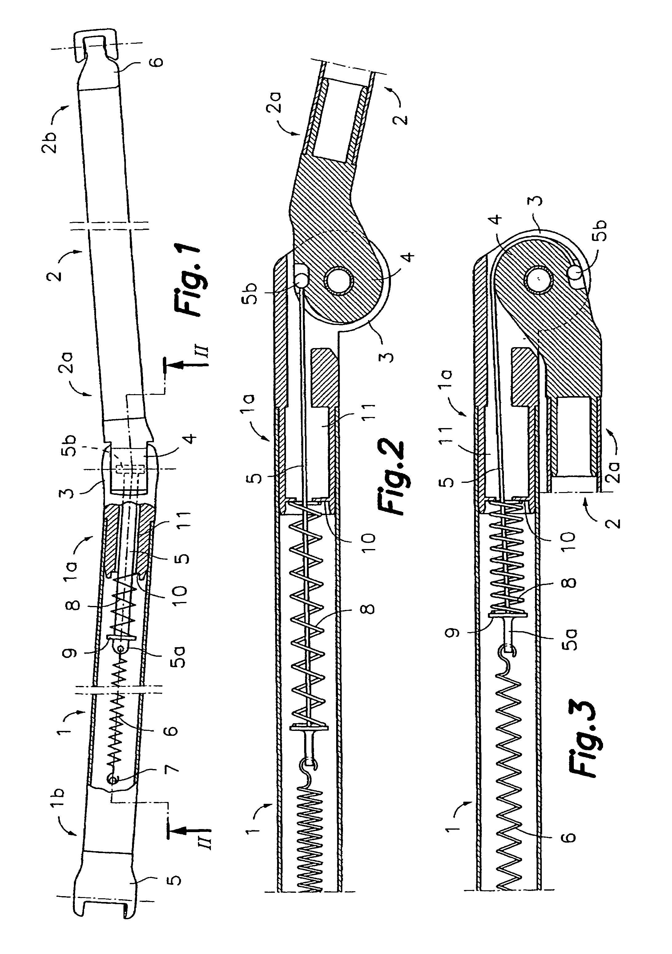
[0014]Referring, in first place, to FIG. 1, the articulated awning arm, with improved elastic effect, in accordance with this invention, comprises an arm 1 and a forearm 2, joined together by means of respective articulation configurations 3, 4 located at adjacent ends 1a, 2a of the same. This articulation forms an elbow that permits the arm and forearm 1, 2 assembly to move between open (shown in FIG. 1) and closed positions. In a typical application, arm 1 has, at its other end 1b, an articulated anchoring configuration 15 for the articulated joint of the arm and forearm assembly 1, 2 to a fixed support, and the forearm 2 terminates at its other end 2b in an articulated support 6 for the articulated connection to an awning loading bar (not shown). The arm and forearm assembly 1,2 moves from the open to the closed positions due to the traction effect of the awning canvas when the same is wound onto a roll-up bar driven either mechanically or manually.

[0015]During the closing moveme...


PUM


Abstract

An articulated arm for awnings is disclosed. The articulated arm comprises an arm and a forearm, joined together by respective articulation configurations located at adjacent ends of the same, which enables them to move between open and closed positions. There is a flexible tie bar inside the arm, with a second end anchored to the articulation configuration of end of the forearm and linked by a first end to an elastic traction element anchored to a fixed point on the arm and an elastic compression element located between a stop on the flexible tie bar and a support of the end of the arm in order to produce tension in the tie bar on moving from the open position to closed, generating torque tending towards the open position.

Description

[0001]This application is a U.S. National Phase Application of PCT International Application No. PCT / ES2003 / 1000408, filed Aug. 5, 2003.FIELD OF THE INVENTION[0002]This invention concerns an articulated arm for an awning with improved elastic effect, equipped with an arm and a forearm that articulate with each other and a flexible tie bar associated with an elastic traction element and an elastic compression element in order to push the arm and forearm into an open position.TECHNICAL BACKGROUND[0003]The articulated arm configuration for an awning that consists of an arm and forearm comprising respective tubular arms with ends terminating in plug-in parts that define articulation configurations is a classic design. The arm and forearm are joined together by means of an articulation formed by two of the said adjacent articulation configurations. Within the profile that makes up the body of the arm is the spring under traction that is joined at one end to a fixed point on the tubular p...

Claims


Application Information

Patent Timeline
Patent Type & Authority Patents(United States)
IPC IPC(8): E04F10/00E04F10/06
CPCE04F10/0611E04F10/0618E04F10/0622E04F10/0651
Inventor LLAGOSTERA FORNS, JOAN
Owner LLAZA
Why Eureka
Try Eureka