Electric drill with modified bit gripping assembly

a technology of electric drills and drive assemblies, which is applied in the direction of power-driven drills, mechanical machines/dredgers, drilling machines and methods, etc., can solve the problems of time-consuming tasks, time-consuming changes, and contractors may suffer back strain in bending over to change bits frequently, etc., and achieves the effect of convenient use with one hand

a technology of electric drills and drive assemblies, which is applied in the direction of power-driven drills, mechanical machines/dredgers, drilling machines and methods, etc., can solve the problems of time-consuming tasks, time-consuming changes, and contractors may suffer back strain in bending over to change bits frequently, etc., and achieves the effect of convenient use with one hand

US7367757B2Inactive Publication Date: 2008-05-06PHILLIPS SEAN PETER

Image

  • Electric drill with modified bit gripping assembly
  • Electric drill with modified bit gripping assembly
  • Electric drill with modified bit gripping assembly

Examples


Embodiment Construction

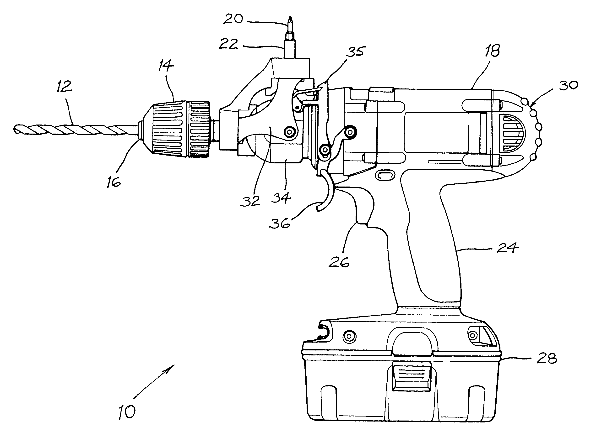
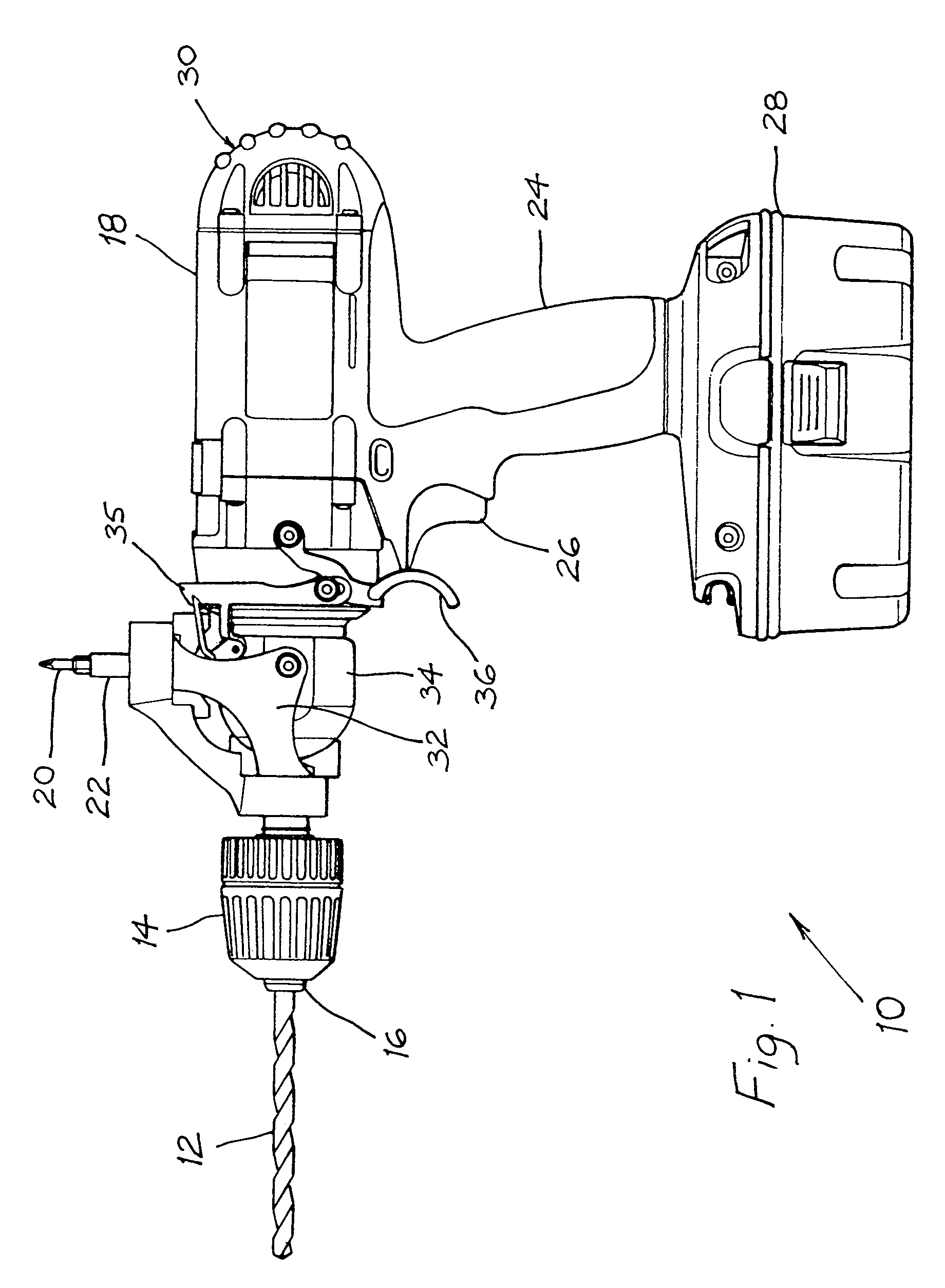
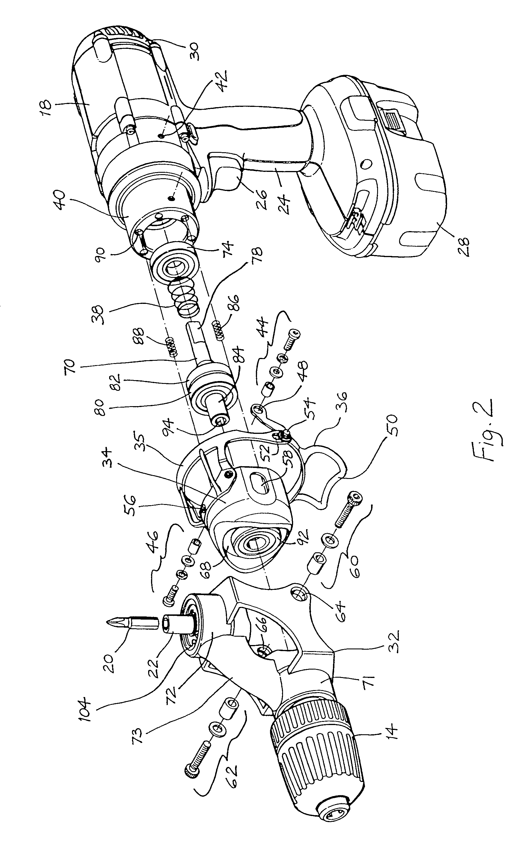
[0021]As shown in FIG. 1, a portable electric drill 10 has a drill bit 12 gripped by a quick release chuck 14 having a three jaw holder 16. The chuck 14 is engaged to a drive assembly, only a forward part of which is shown in FIGS. 2, 4 and 6. Disposed at 90 degrees to the quick release chuck 14 is a screw bit 20 gripped by a bit holder 22. There are means (to be hereinafter described in detail with reference to FIGS. 2 to 6) for adjusting the position of each of the chuck 14 and bit holder 22 relative to the drive assembly, whereby a selected one of these two preferred bit gripping assemblies may be operatively engaged to the drive assembly.

[0022]The drill 10 also includes a handle 24 with a trigger 26 for actuating the drive assembly, and a battery pack 28 for supplying power thereto. The body 18 houses an electric motor (not shown) at its rearward end 30, a gear box and torque clutch assembly (not shown), and a main drive shaft 31 (partly shown in FIGS. 4 and 6) between the gear ...


PUM

PropertyMeasurementUnit
structureaaaaaaaaaa
poweraaaaaaaaaa
energyaaaaaaaaaa

Abstract

An electric drill (10) has a drive assembly (31, 70), and a pivot head (32) having first and second bit gripping assemblies (14, 22) disposed at 90 degrees to each other. The electric drill (10) also includes means for adjusting the position of the bit gripping assemblies (14, 22) relative to the drive assembly (31, 70) by pivoting the head (32) through 90 degrees, whereby a selected one of the bit gripping assemblies is operatively engaged to the drive assembly. The position adjusting means may include a movable locking sleeve (36) which, in a first position, allows the drive assembly to operatively engage the selected bit gripping assembly and, in a second position, allows the drive assembly to disengage the selected bit gripping assembly.

Description

FIELD OF THE INVENTION[0001]The present invention relates to improvements in electric drills and, in particular, to a portable electric drill having a modified bit gripping and drive assembly.BACKGROUND OF THE INVENTION[0002]Building contractors in the construction industry, and especially carpenters, are often required to install a large number of fasteners in walls or other reference surfaces. Unless the fastener is self-tapping, or splitting of the surfaces is tolerated, a pilot hole must first be drilled in the reference surface before the fastener is driven therethrough. This is normally achieved by using two electric drills, or by using a single electric drill and firstly using a drill bit fitted to the chuck of the electric drill to drill the pilot hole, and then removing the drill bit and fitting a screw bit to the chuck or removing the chuck altogether and installing a bit holder with fitted screw bit to the drive assembly of the electric drill. This is a time consuming tas...

Claims


Application Information

Patent Timeline
06 May 2008
Publication
US7367757B2
IPC
B23B45/00
CPC
B23B45/003; B25B21/00; B25B21/007; B25F3/00; Y10T408/37; Y10T408/65; Y10T408/60
Inventors
PHILLIPS, SEAN PETER