Polymerase chain reaction using metallic glass-coated microwire

a technology of polymerase chain reaction and microwire, which is applied in the direction of film/foil adhesive, magnetic body, biomass after-treatment, etc., can solve the problems of generating numerous copies of irrelevant, erroneous conclusions, and product rendering useless

Inactive Publication Date: 2008-05-06
DEMODULATION
View PDF4 Cites 4 Cited by
  • Summary
  • Abstract
  • Description
  • Claims
  • Application Information

AI Technical Summary

Benefits of technology

[0013]In accordance with the invention, there is provided a composite device whereby the components of the PCR reaction are either: a) loaded or encapsulated into nano- or microporous glass that is part of the microwire itself; b) maintained at the surface via entrapment in a hydrogel-like layer. By placing the PCR reaction system near or at the surface of the MGCM, DNA target molecules, or DNA-containing systems may be acquired from the environment and the DNA so obtained will form the substrate for DNA amplification via PCR. A successful PCR event will also require thermal cycling to amplify the DNA and some form of detection of the DNA product. The MGCM system itself can act as the thermal cycling component of the PCR machine via induced heating and cooling. Detection can be accomplished photonically, spectrophotometrically or electromagnetically, based on the intrinsic properties of the glass and metal components of the system. The result of this invention is a micro-scale, self-contained PCR system that is capable of conducting the PCR (or the RT-PCR) reaction, detecting PCR products, and transmitting a signal that indicates whether or not a nucleic acid amplification event has occurred. This system is scalable, with the bundling of multiple MGCM wires or the ‘bar-coding’ of multiple sites on single microwires sufficient to create highly, or massively parallel systems.

Problems solved by technology

Such an investigation requires, however, that enough of the DNA under study is available for analysis, which is the issue that PCR addresses.
One of the most troublesome technical problems encountered with PCR involves contamination of the sample with extraneous genetic material, thereby generating numerous copies of irrelevant DNA.
When such contamination occurs, the resulting product is rendered useless; and oftentimes leads erroneous conclusions.
For example, mistaken activation of a PCR-based bioweapons sensor could result in mobilization of defense forces or heighten public anxiety due to inaccurate information predicting a bioweapons-based attack.

Method used


Image

  • Polymerase chain reaction using metallic glass-coated microwire
  • Polymerase chain reaction using metallic glass-coated microwire
  • Polymerase chain reaction using metallic glass-coated microwire

Examples


example 1

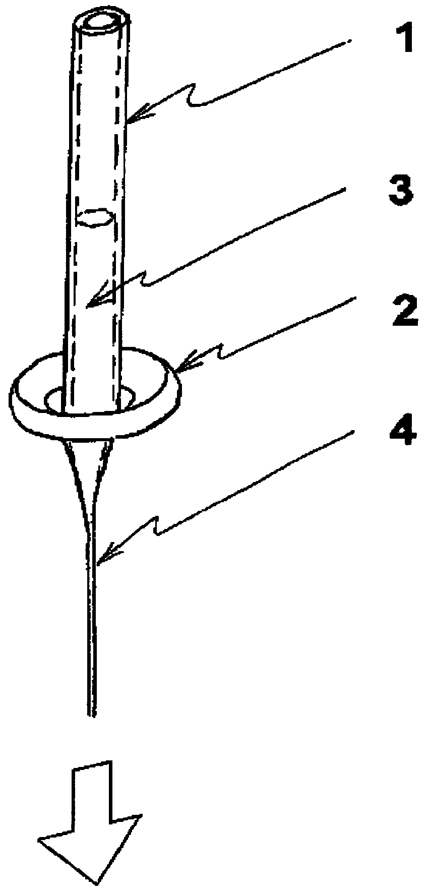
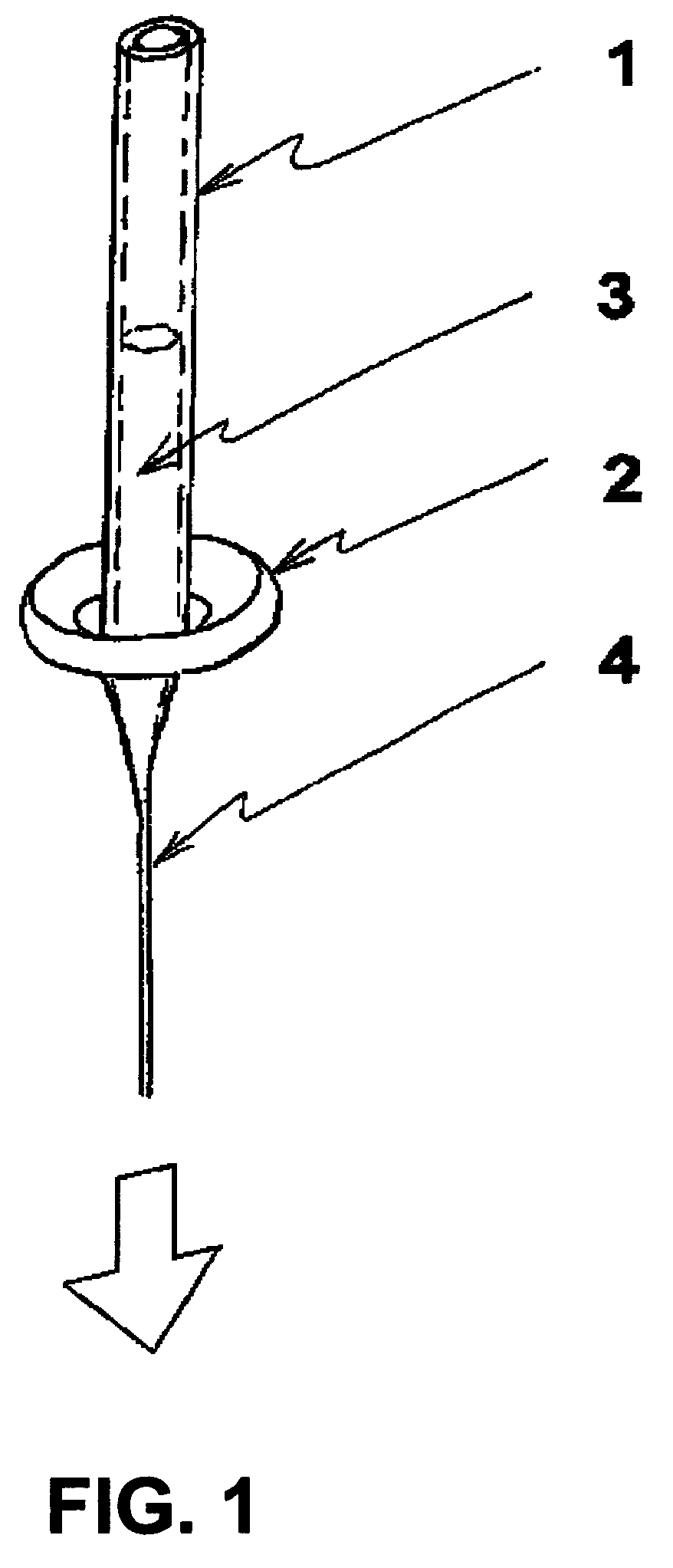
[0045]An ingot composed of an amorphous-forming metallic alloy is prepared by loading the appropriate weights of constituent elements into a quartz tube that is sealed at one end. The other end of this quartz tube is connected to a pressure-vacuum system to allow evacuation and back filling with Ar gas several times to ensure a low oxygen Ar atmosphere within the quartz tube. Next, the closed end of the quartz tube in which the elements reside is introduced into a high frequency induction-heating coil. With the application of radio frequency (“r.f.”) power, the elements inside the tube are caused to heat and melt into a stirred, homogeneous metallic alloy body. When the r.f. power is shut off, the alloy body is allowed to cool to room temperature in the Ar atmosphere. Once cooled, the same metallic alloy body is inserted into the bottom of a vertically disposed glass tube 1 (preform), having 6-mm diameter that is sealed at the lower end, as depicted in FIG. 1. The upper end of this ...

example 2

[0050]An ingot of copper is inserted into the bottom of a vertically disposed glass tube 1 (preform) that has a 6-mm diameter and is sealed at the lower end, as depicted in FIG. 1. The upper end of this preform is connected to a pressure-vacuum system to allow evacuation and back filling with Ar gas several times to ensure a low oxygen Ar atmosphere within the quartz tube. A specially built inductor 2 at the bottom of the preform is energized with r.f. power in order to heat and then melt the metallic alloy body 3 within the tube. Once the ingot is molten and sufficiently heated above its melting temperature, a solid glass rod is used to touch and bond to the bottom of the sealed glass preform in which the molten copper resides. The heat of the molten copper softens the glass preform, allowing it to be drawn by pulling on the glass rod to which it is attached. Molten copper is entrained in the drawn glass capillary 4 that results. The drawn capillary is then pulled and guided onto a...

example 3

[0055]MGCM having a copper core is produced per the procedure of Example 2. The post-drawing process, shown in FIG. 3, begins with 55 wt. % H2SO4 introduced into buret (1) to be followed by and evaporation flask 2 to which air 3 is also added. The acid / air mixture in this flask is heated using a hot plate 4 to create acid vapor, which is introduced into a thermally insulated oven 5 containing the MGCM for treatment at 550° C. for 30 minutes. Acid vapor is flowed continuously for the treatment time and is cleansed using a condenser 6 before being liberated 7. In the present example the glass surface is simultaneously transformed to have multiple phases and leached during the heat treatment during a single step operation.


PUM

PropertyMeasurementUnit
surface porosityaaaaaaaaaa

Abstract

A metallic glass-coated microwire has controllable surface porosity. The porosity is achieved by etching the metallic glass-coated microwire or other shapes of glass-coated bodies with acid after annealing to produce a multi-phase glass coating. Porous metallic glass-coated microwires are found to make superior PCR machines, which find use in a variety of in vivo, biochemical, and chemical sensors. Advantageously, the PCR apparatus is smaller, less expensive to construct than conventional units. It readily carries out in vivo passive or active operations.

Description

RELATED U.S. APPLICATION DATA[0001]This application claims the benefit of U.S. Provisional Application No.: 60 / 559,995, filed Apr. 6, 2004.BACKGROUND OF THE INVENTION[0002]1. Field of the Invention[0003]This invention relates to the use of metallic glass-coated microwire (MGCM) in support of a polymerase chain reaction (PCR); and more particularly, to a micro-scale, self-contained PCR system that is capable of conducting the PCR (or an RT-PCR) reaction, detecting PCR products, and transmitting a signal that indicates whether or not a nucleic acid amplification event has occurred.[0004]2. Description of the Prior Art[0005]The genetic material of each living organism, whether plant or animal, bacterium or virus, possesses sequences of its nucleotide building blocks (usually DNA, sometimes RNA) that are uniquely and specifically present only in its own species. Indeed, complex organisms such as human beings possess DNA sequences that are uniquely and specifically present only in partic...

Claims


Application Information

Patent Timeline
Patent Type & Authority Patents(United States)
IPC IPC(8): B32B15/00B05D5/12H01B3/10A61B17/00B01L3/00B01L7/00C12M1/34C12Q1/68H01L21/00
CPCB01L3/502715B01L3/561B01L7/52B01L3/502707A61B2017/008Y10T428/2933B01L3/50851B01L2200/12B01L2200/16B01L2300/0838B01L2300/0845B01L2300/16B01L2300/1827C12Q1/686Y10T428/2958Y10T428/294
Inventor GOLDSTEIN, ALAN H.LACOURSE, WILLIAM C.LIEBERMANN, HOWARD H.
Owner DEMODULATION
Why Eureka
Try Eureka