Acoustic apparatus

a technology of acoustic equipment and acoustic reverb, which is applied in the direction of deaf-aid sets, transducer details, electrical transducers, etc., can solve the problems of loss of acoustic pressure and a drop of treble, inability to respond to a large output, and inability to acquire acoustic re-producing ability which ordinary speakers in themselves have in their own right, so as to achieve good acoustic characteristics

Inactive Publication Date: 2008-05-06
CITIZEN ELECTRONICS CO LTD
View PDF18 Cites 28 Cited by
  • Summary
  • Abstract
  • Description
  • Claims
  • Application Information

AI Technical Summary

Benefits of technology

[0010]The present invention has been made in view of the above problems and an object thereof is to provide an acoustic apparatus having good acoustic characteristics and capable of obtaining matching effect of sound and image.

Problems solved by technology

However, because the conventional mobile phone as described above has a structure hearing a sound from the speaker remote from the image plane in the back surface of the mobile phone while watching an image on the front surface of the mobile phone and the sound hears from a position remote from the image, there are problems that matching effect of sound and image is not acquired, a loss of acoustic pressure and a drop of treble occur, and acoustic re-producing ability which ordinary speakers have in themselves is not acquired.
In the speaker having the structure disclosed in the above-mentioned patent document, because a thickness of a film as a vibrating plate is thinner, there are problems that it has a boundary for an output of the receiver, is suitable for a talking speaker, but cannot respond to a large output as a speaker aimed at a call waiting tone or beep.
This results in an acoustic apparatus having a great thickness.

Method used


Image

  • Acoustic apparatus
  • Acoustic apparatus
  • Acoustic apparatus

Examples


Embodiment Construction

[0023]Some embodiments of the present invention will be explained with reference to the accompanying drawings below.

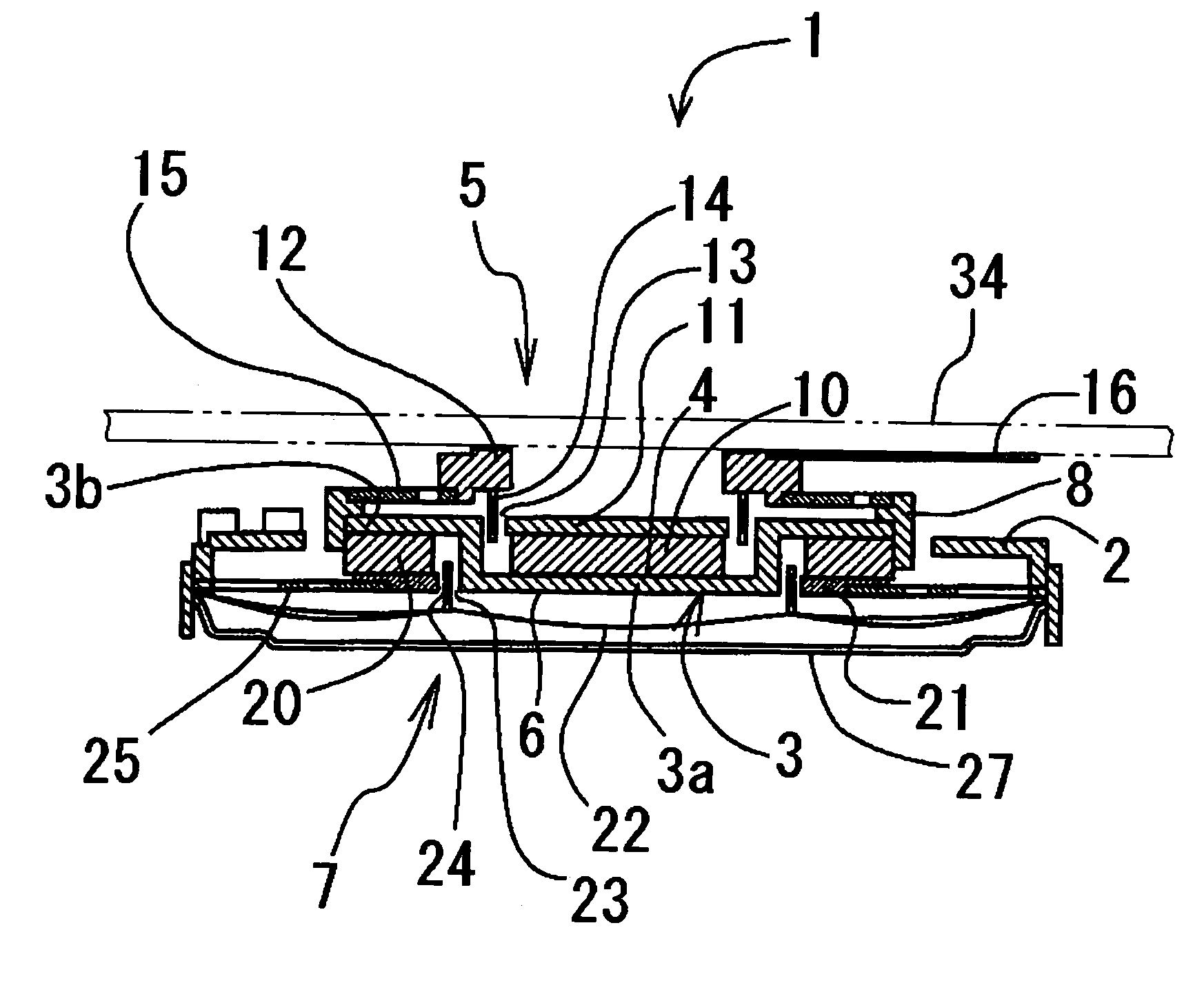
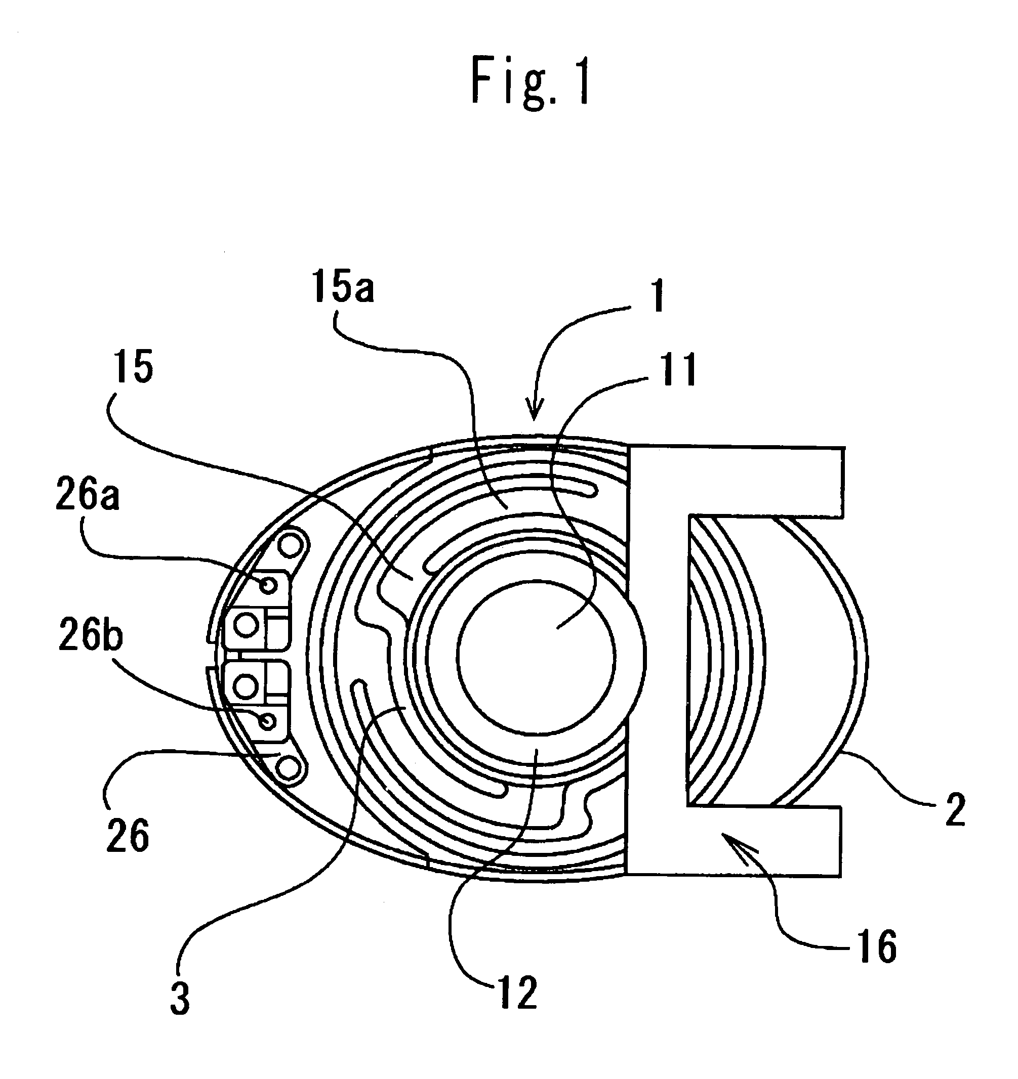
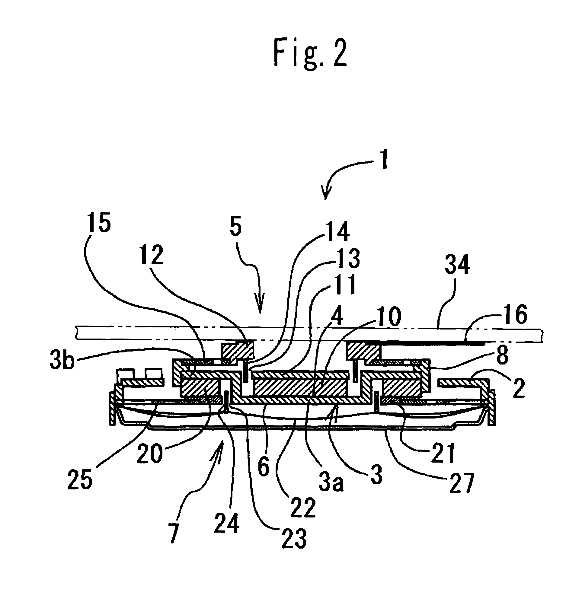
[0024]One embodiment of an acoustic apparatus according to the present invention is illustrated in FIGS. 1 to 3. The acoustic apparatus 1 has both functions to work as an actuator and as a speaker adapted to use suitably for, for example, a communication device such as a mobile phone or mobile terminal.

[0025]The acoustic apparatus 1 comprises a frame 2, a yoke 3 disposed inside of the frame 2, a main speaker mechanism 5 disposed on a first surface 4 of the yoke 3, and a sub speaker mechanism 7 which is disposed on a second surface 6 of the yoke 3 opposite to the first surface 4 adjacent to the main speaker mechanism 5 and integrally with it.

[0026]The main speaker mechanism 5 of an acoustic apparatus has functions of reproducing any type of sound such as TV sounds, game sounds, music, ringing tone, and talking voice as a receiver. Therefore, if the vibrating member whic...


PUM


Abstract

An acoustic apparatus comprising a yoke, a main speaker mechanism disposed on a first surface of the yoke, and a sub speaker mechanism disposed on a second surface of the yoke opposite to the first surface and adjacent to the main speaker mechanism, the main speaker mechanism including a first magnet disposed on the first surface of the yoke, a first top plate disposed on the first magnet, a vibration-transmitting panel attached to the yoke and contactable with a vibrating member in a communication device, and a first voice coil attached to the vibration-transmitting panel and inserted in a first magnetic gap formed between the yoke and the first magnet, the sub speaker mechanism including a second magnet disposed on the second surface of the yoke, a second top plate disposed on the second magnet, a vibrating plate attached to a frame disposed to surround the yoke and a second voice coil attached to the vibrating plate and inserted in a second magnetic gap formed between the yoke and the second magnet.

Description

CROSS-REFERENCE TO THE RELATED APPLICATION[0001]The application claims the priority benefit of Japanese Patent Application No. 2003-391518, filed on Nov. 20, 2003, the entire descriptions of which are incorporated herein by reference.BACKGROUND OF THE INVENTION[0002]1. Field of the Invention[0003]The present invention relates to an acoustic apparatus suitable for communication devices such as a mobile phone, portable television, and computers.[0004]2. Description of Related Art[0005]Conventionally, an acoustic outputting apparatus for a mobile phone is composed of two speakers in general. One example of such a conventional mobile phone is described referring to FIG. 5A to 5C. In FIGS. 5A to 5C, the mobile phone 51 has a display 51a, an operational part 51b, and a liquid crystal display 52, which is disposed on a front surface of the display 51a and corresponds to an image plane. Numeral 53 denotes a speaker for talking, which is disposed on the front surface of the display 51a outsi...

Claims


Application Information

Patent Timeline
Patent Type & Authority Patents(United States)
IPC IPC(8): H04R25/00H04R9/02H04R1/02H04R1/26H04R9/10
CPCH04R9/10H04R9/025H04R2499/15
Inventor MIURA, NAOKI
Owner CITIZEN ELECTRONICS CO LTD
Why Eureka
Try Eureka