High speed piezoelectric optical system with tunable focal length

a piezoelectric and optical system technology, applied in the field of optical systems, can solve the problems of changing the curvature of the membrane and the focal length of the optical element, and achieve the effect of modifying the curvature of the membrane and altering the focal length of the lens

Active Publication Date: 2008-05-06
CHARLES STARK DRAPER LABORATORY
View PDF4 Cites 72 Cited by
  • Summary
  • Abstract
  • Description
  • Claims
  • Application Information

AI Technical Summary

Benefits of technology

[0016]In an alternative embodiment, the present invention features a varifocal lens that includes a volume of refractive liquid characterized by a focal length and a curvature. At least one membrane, described in paragraph 13 above, forms one or more boundaries of the volume of refractive liquid. A ...

Problems solved by technology

This results in a change in the curvature of the membrane, and...

Method used


Image

  • High speed piezoelectric optical system with tunable focal length
  • High speed piezoelectric optical system with tunable focal length
  • High speed piezoelectric optical system with tunable focal length

Examples


Embodiment Construction

[0030]The present invention uses thin film piezoelectric technology to deform relatively stiff plates so as to achieve high-frequency deformable optical components. In particular, the present invention features high speed micro-optical components whose focal length is controlled by piezoelectric actuation of thin-film PZT. Tuning ranges of several hundred microns have been achieved. High speed micro-optical components in accordance with the present invention are useful for a variety of applications in which high-speed focal-length variability is required, including but not limited to optical switching applications, and high-speed confocal microscopy.

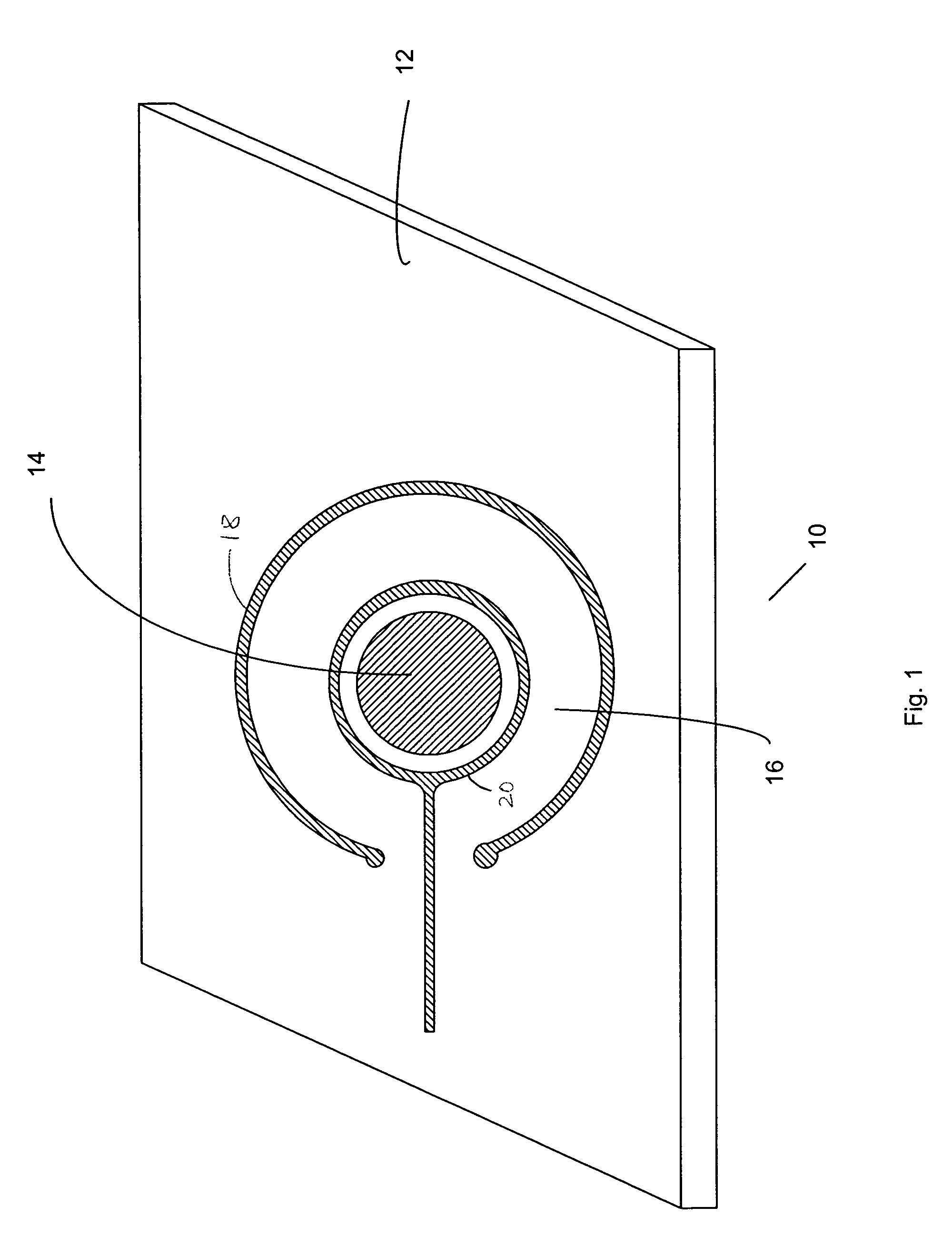
[0031]FIG. 1 illustrates a schematic overview of a varifocal optical system 10, constructed in accordance with one embodiment of the present invention. In overview, the varifocal optical system 10 includes a substrate 12, a membrane 14, and a piezoelectric thin film 16 deposited on at least a portion of the surface of the membrane 14. Th...


PUM

PropertyMeasurementUnit
Lengthaaaaaaaaaa
Lengthaaaaaaaaaa
Thicknessaaaaaaaaaa

Abstract

A varifocal optical system includes a substantially circular membrane deposited on a substrate, and a ring-shaped PZT thin film deposited on the outer portion of the circular membrane. The membrane may be a MEMS-micromachined membrane, made of thermal oxide, polysilicon, ZrO2 and SiO2. The membrane is initially in a buckled state, and may function as a mirror or a lens. Application of an electric voltage between an inner and outer electrode on the piezoelectric thin film induces a lateral strain on the PZT thin film, thereby altering the curvature of the membrane, and thus its focal length. Focal length tuning speeds as high as 1 MHz have been demonstrated. Tuning ranges of several hundred microns have been attained. The varifocal optical system can be used in many applications that require rapid focal length tuning, such as optical switching, scanning confocal microscopy, and vibration compensation in optical storage disks.

Description

CROSS REFERENCES TO RELATED APPLICATIONS[0001]This application claims the benefit of priority under 35 U.S.C. §119(e) from commonly owned U.S. provisional patent application Ser. No. 60 / 348,136, entitled “Piezoelectric Deformable Varifocal Mirror, and filed on Nov. 9, 2001.STATEMENT OF GOVERNMENT INTEREST[0002]The U.S. Government has no interest in or to this patent.FIELD OF THE INVENTION[0003]The present invention relates to optical systems, and in particular relates to a high speed, piezoelectrically actuated optical system with tunable focal length.BACKGROUND[0004]There is a growing demand for optical elements having tunable focal lengths, including adaptive optics systems. For example, adaptive optics technology is used in astronomy in order to overcome significant limitations in the image quality of telescopes, caused by atmospheric turbulence. Also, most optical systems have defects in construction or factors in their environment that prevent them from operating optimally. The...

Claims


Application Information

Patent Timeline
IPC IPC(8): G02B6/32
CPCG02B3/14G02B26/0875G02B26/0825Y10T29/42
Inventor MESCHER, MARK J.
Owner CHARLES STARK DRAPER LABORATORY
Why Eureka
Try Eureka