
Process for three-dimensional modeling and design of off-highway dump bodies

Inactive Publication Date: 2008-05-06
PHILIPPI HAGENBUCH
View PDF22 Cites 15 Cited by
  • Summary
  • Abstract
  • Description
  • Claims
  • Application Information

AI Technical Summary

Benefits of technology

[0011]A related object is to provide a method for designing off-highway dump bodies which more accurately takes into account actual field conditions.

Problems solved by technology

Historically, off-highway truck manufacturers have been unable to reach a consensus with regards to the theoretical load heaps or configurations, let alone any consensus on the individual hauled material characteristics that should be used to design the dump bodies.
For example, theoretical load profiles do not take into account the particular material characteristics of the material being loaded and hauled.
In addition, theoretical load profiles do not take into account the corner voids which occur when a load is placed in the dump body.
Additionally, field loading / haulage conditions impact the actual angles of repose that the loaded material forms in the dump body.
As a result, the mass-produced dump bodies supplied by off-highway truck manufacturers which are based on a theoretical material load profile are often improperly matched for a particular material haulage application.
This causes incorrect truck loading and improper truck utilization with uneven loading of the truck chassis leading to uneven or offset frame loading, which can potentially result in truck chassis problems including uneven tire wear which often requires premature replacement of the tires; and potentially poor vehicle operating stability.
As will be appreciated, since the trucks themselves and the tires used on these types of off-highway trucks are extremely costly, potential truck chassis repair and premature replacement of tires significantly increases the operating expenses associated with material haulage.
Likewise, depending on how the actual material and material heap varies from a theoretical material load profile, the dump body can be either too large or too small resulting in the truck chassis carrying loads which are both improperly placed on the truck frame and significantly heavier or lighter than intended.
An improperly designed body which is too small to carry the intended load can lead to spillage of the load over the sides and off the rear end of the body resulting in significant under utilization of the truck.
If side / rear spillage occurs during transport, it can result in tire damage and tire ruptures particularly on the following trucks.
While too large of a body for the intended load can result in extreme truck overloads or if the load is limited to the correct load amount in the dump body, the load may often be improperly placed in the dump body leading to poor truck stability and individual truck chassis component overloads.

Method used


Image

  • Process for three-dimensional modeling and design of off-highway dump bodies
  • Process for three-dimensional modeling and design of off-highway dump bodies
  • Process for three-dimensional modeling and design of off-highway dump bodies

Examples


Embodiment Construction

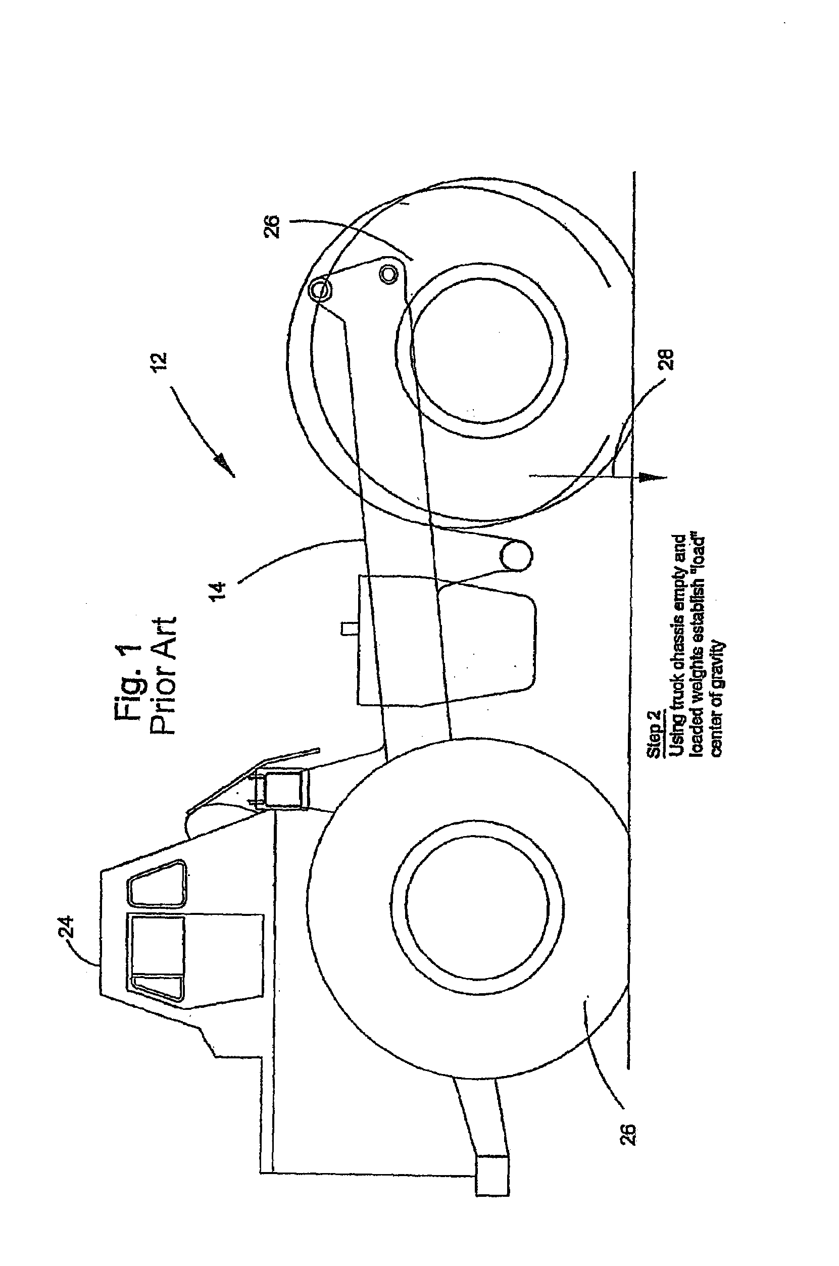
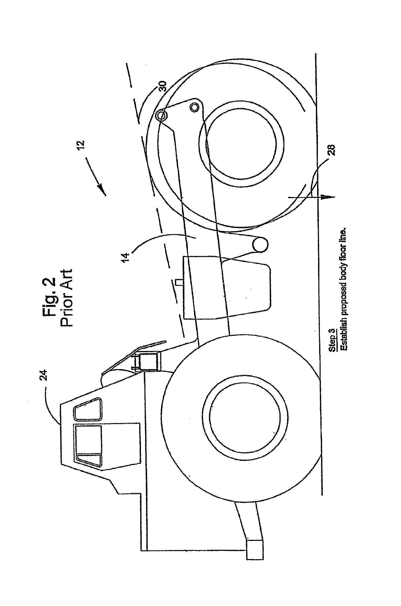
[0035]Referring now more particularly to the drawings there is shown in FIGS. 1-17 an illustrative sequence of process steps for designing a dump body 10 for an heavy-duty off-highway truck 12 in accordance with the teachings of the present invention. The truck 12 includes a chassis 14 to which the dump body 10 is attached for pivotal movement about an axis between a lowered position for receiving and transporting a load of material and a raised position for dumping a load of material. As shown in FIG. 17, the dump body 10 is generally constructed of steel panels which define the shape of the dump body and beams which form the structural framework for the dump body. The dump body comprises, in this case, sidewalls 16, a front wall or front slope 18, a floor 20 and a canopy 22 integrally connected to the top end of the front slope 18 and extending over the cab 24 of the truck 12. The truck chassis 14 is supported by a plurality of tires 26.

[0036]In the illustrated embodiment, the tru...


PUM


Abstract

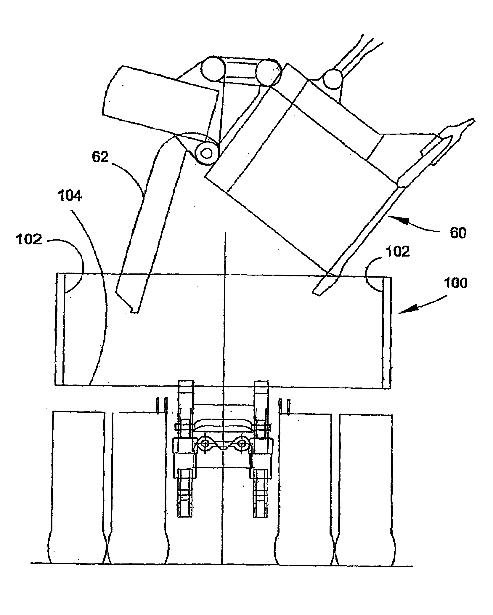
A method of loading material into a dump body of a truck using a loading bucket whose volumetric capacity is approximately ⅓ or more than that of the dump body is provided. The dump body having side walls that are spaced relatively wider than conventional dump bodies. The loading bucket having a gate at a lower end thereof that when free swings open and causes the material contained in the loading bucket to drop into the dump body. The method including the steps of filling the loading bucket with an amount of earthen material and centering the loading bucket over the dump body. The bucket is then lowered to a position that: (1) substantially minimizes the clearance between the floor of the dump body and the swinging gate in its freed position; (2) allows the swinging gate to clear the side walls of the dump body as it swings through an arc after it is freed, and (3) allows the material to be discharged substantially in the center of the dump body. The swinging gate is then freed so as to open the bucket and allow the material held in the bucket to drop into the dump body.

Description

CROSS-REFERENCE TO RELATED APPLICATIONS[0001]This application is a continuation-in-part of Ser. No. 09 / 333,379 filed Jun. 15, 1999.FIELD OF THE INVENTION[0002]The present invention relates generally to heavy-duty off-highway trucks, and more particularly to a process for designing an off-highway truck dump body.BACKGROUND OF THE INVENTION[0003]In mining and construction environments, heavy-duty off-highway trucks are used to haul a variety of materials such as, for example, coal, rock, ore, and overburden materials. Such heavy-duty off-highway trucks generally comprise a truck chassis or frame which supports a dump body for receiving and carrying a load. In order to ensure that the dump body is properly balanced, the dump body should be designed based on an anticipated load distribution of the material carried on the truck chassis or frame. More specifically, the truck chassis anticipates a particular optimal location on the chassis where the center of gravity of the load carried in...

Claims


Application Information

Patent Timeline
IPC IPC(8): G06G7/48B60P1/00B62D33/02G06T19/00
CPCG06F17/5095G06T19/00B60P1/28G06F30/15
Inventor HAGENBUCH, LEROY G.BRINKMAN, PHILIP T.
Owner PHILIPPI HAGENBUCH
Learn More