Thermal monitoring and response apparatus and method for computer unit

a technology of response apparatus and computer unit, which is applied in the direction of instruments, heat measurement, digital computer details, etc., to achieve the effects of ensuring reliable system operation, reducing maintenance costs, and increasing uptim

Active Publication Date: 2008-05-06
NETWORK APPLIANCE INC
View PDF16 Cites 23 Cited by
  • Summary
  • Abstract
  • Description
  • Claims
  • Application Information

AI Technical Summary

Benefits of technology

[0010]The present invention uses multiple thermal sensors positioned strategically inside the enclosure of a computer unit to sense the temperature of the important heat-generating components and subsystems as well as the system itself. The indications from the sensors are interpreted and correlated to make reliable thermal response decisions without solely depending on the indications from individual sensors and on the individual limits for each of the sensors. The very important system-level responses are based on correlated consideration of the temperature indications from other sensors. The thermal condition of the entire computer unit is better evaluated and monitored during continuous operation. Occasional sensor errors are recognized as such to avoid unnecessary system shutdowns and slowdowns in operation and to avoid false warnings of impending problems, when actual problems do not exist or were transitory nature and have resolved themselves. Permanent sensor errors may still allow continued system operation under some circumstances if the correlated analysis of other temperature signals from other sensors indicate acceptable operating conditions. The technique is adaptable to the existing infrastructure of most computer units and their installation sites. Reliable system operation is assured, uptime is increased, and maintenance costs are reduced.

Problems solved by technology

Permanent sensor errors may still allow continued system operation under some circumstances if the correlated analysis of other temperature signals from other sensors indicate acceptable operating conditions.

Method used


Image

  • Thermal monitoring and response apparatus and method for computer unit
  • Thermal monitoring and response apparatus and method for computer unit
  • Thermal monitoring and response apparatus and method for computer unit

Examples


Embodiment Construction

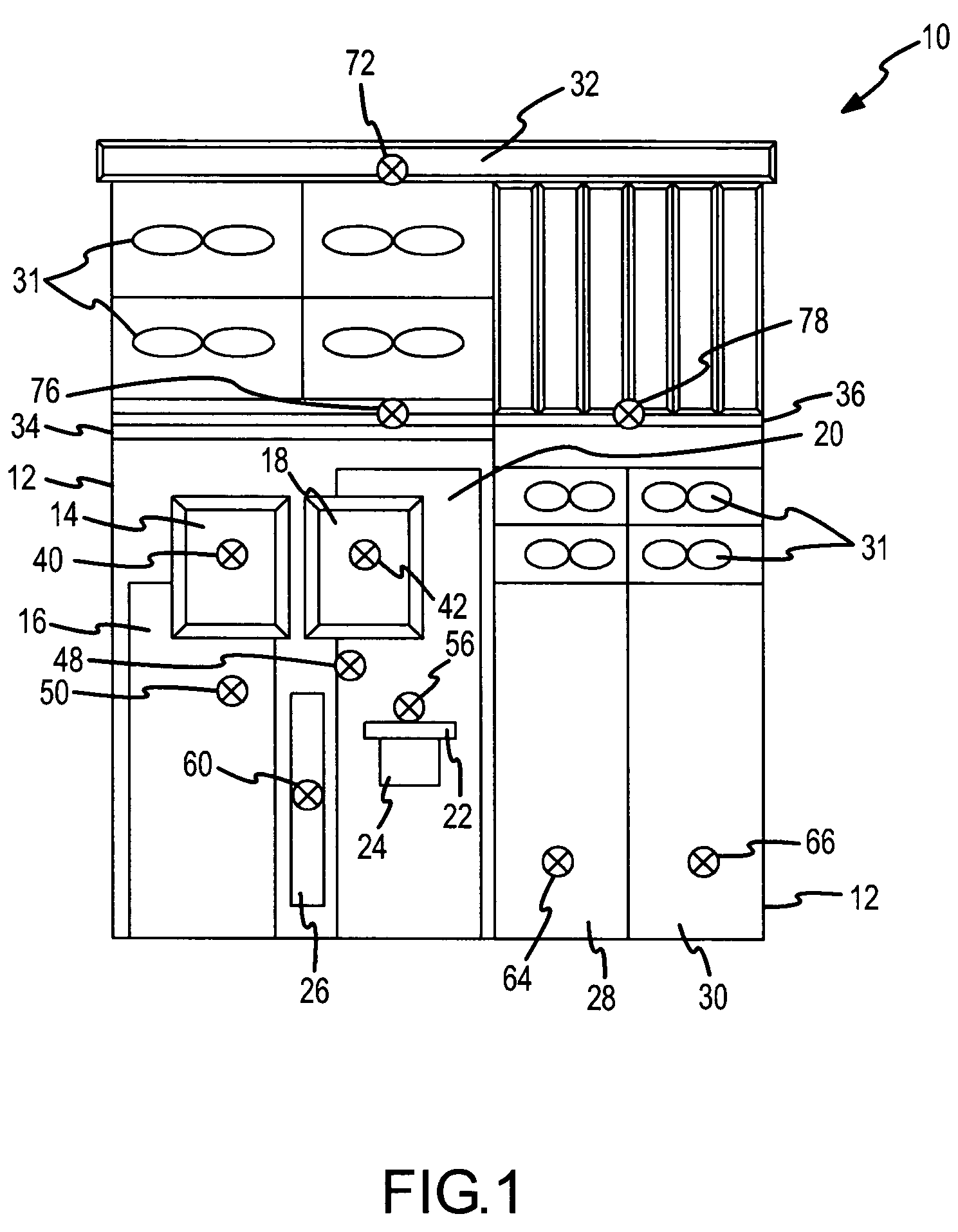
[0019]Details of the present invention are illustrated in connection with a computer unit 10, such as a network storage server, shown in FIG. 1. The computer unit 10 includes an external case or enclosure 12 within which components of the computer unit 10 are located and housed. Those components include at least one central processing unit (CPU) 14 connected to or associated with a motherboard 16. Preferably, the computer unit 10 also includes a second CPU 18 which is connected to or associated with a second motherboard 20. Both CPUs 14 and 18 could be included on a single motherboard 16 or 20. One of the motherboards, for example motherboard 20, includes a data-transfer bus 22, such as a conventional PCI bus, to which there is connected a conventional bus device 24, such as a nonvolatile memory card, for example. The bus device 24 is added to or used in conjunction with the computer unit 10 on an optional basis. The bus device 24 may turn the computer unit 10 into a specific use co...


PUM


Abstract

Thermal conditions within a computer unit are monitored. A system-level temperature sensor responds to intake cooling air. A subsystem-level temperature sensor responds to the temperature of a subsystem-level component, preferably a motherboard or a backplane. When the temperature sensed by of the system-level temperature sensor falls outside of a critical limit, it is determined whether the temperature sensed by the subsystem-level temperature sensor generally correlates with the temperature sensed by the system-level temperature sensor. If there is no correlation, the operation of the computer unit is continued.

Description

[0001]This invention relates to computers and is particularly useful for computer units which are required to be continuously available to act on relatively massive, mission-critical data, such as network storage servers and enterprise servers. More particularly, the present invention relates to a new and improved apparatus and method for more reliably monitoring thermal conditions of the computer at the component, subsystem and system levels in such a way to detect legitimate abnormal thermal conditions and respond to protect the computer unit from damage while simultaneously recognizing false abnormal thermal conditions and responding by maintain full functionality of the computer unit rather than unnecessarily alarming, slowing or terminating operation of the computer unit under such false abnormal thermal conditions.BACKGROUND OF THE INVENTION[0002]Computer units generate heat as a result of conducting electrical currents within their various semiconductor integrated circuits, p...

Claims


Application Information

Patent Timeline
Patent Type & Authority Patents(United States)
IPC IPC(8): G06F11/00
CPCG06F1/20G06F1/206
Inventor CHEN, CHIH-YIXIONG, GUOHUARATTY, MUTHUKUMAR
Owner NETWORK APPLIANCE INC
Why Eureka
Try Eureka