Rider restraint apparatus

a technology for restraints and riders, applied in safety belts, bicycle equipment, pedestrian/occupant safety arrangements, etc., can solve the problems of many assembly hours, many components, and manual operation of the restraint, so as to reduce the length of assembly hours, the effect of increasing productivity

Inactive Publication Date: 2008-05-13
HONDA MOTOR CO LTD
View PDF24 Cites 9 Cited by
  • Summary
  • Abstract
  • Description
  • Claims
  • Application Information

AI Technical Summary

Benefits of technology

[0008]The present invention was made in the light of the aforementioned problems, and an object of the present invention is to provide a rider restraint apparatus which can allow a rider to leave a vehicle quickly without a manual release operation when there is no need to restrain the rider to the vehicle and which is excellent in productivity with fewer electronic components and fewer assembly hours needed.
[0014]According to the first aspect of the present invention, the coupling is released when a secondary motion occurs during rapid deceleration at collision or the like, and it is possible to reduce an influence of the secondary motion on the rider. Moreover, in the case of comparatively low speed where the secondary motion is less likely to occur, the rider can leave the vehicle quickly without a manual operation to release the coupling.
[0015]According to the second aspect of the present invention, a plurality of the detachable devices and a plurality of the coupling release devices are provided. Accordingly, it is possible to restrain the rider more quickly than the case with a piece of the detachable device and a piece of the coupling release device when it is required to restrain the rider. Furthermore, it is possible to release the restraint more quickly than the case with a piece of the detachable device and a piece of the coupling release device when the restraint of the rider becomes unnecessary.
[0017]According to the fourth aspect of the present invention, the apparatus is not electrically controlled so that it can release the coupling without the need for electricity. Moreover, the number of components and the length of assembly hours can be reduced, thus increasing the productivity.
[0018]According to the fifth aspect of the present invention, the wire is covered with the outer tube, and the possibility of laying out the wire is increased.

Problems solved by technology

Therefore, this structure is problematic in that many components and many assembly hours are needed due to the control of the electrical elements.
In addition, when a rider wants to leave the vehicle quickly when the vehicle is being operated at a comparatively low speed where secondary motion is less likely to occur, there is a problem in that a manual operation to release the restraint is required.

Method used


Image

  • Rider restraint apparatus
  • Rider restraint apparatus
  • Rider restraint apparatus

Examples


Embodiment Construction

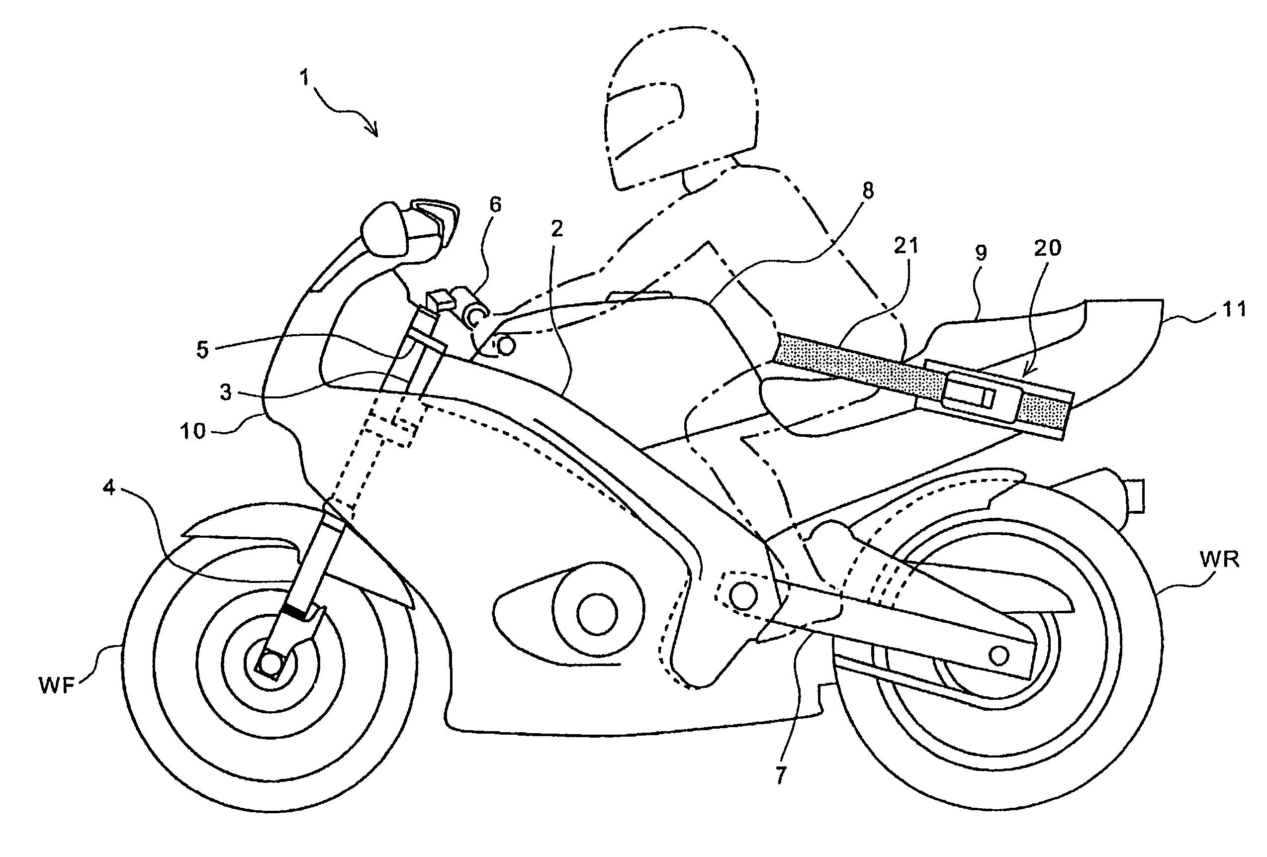
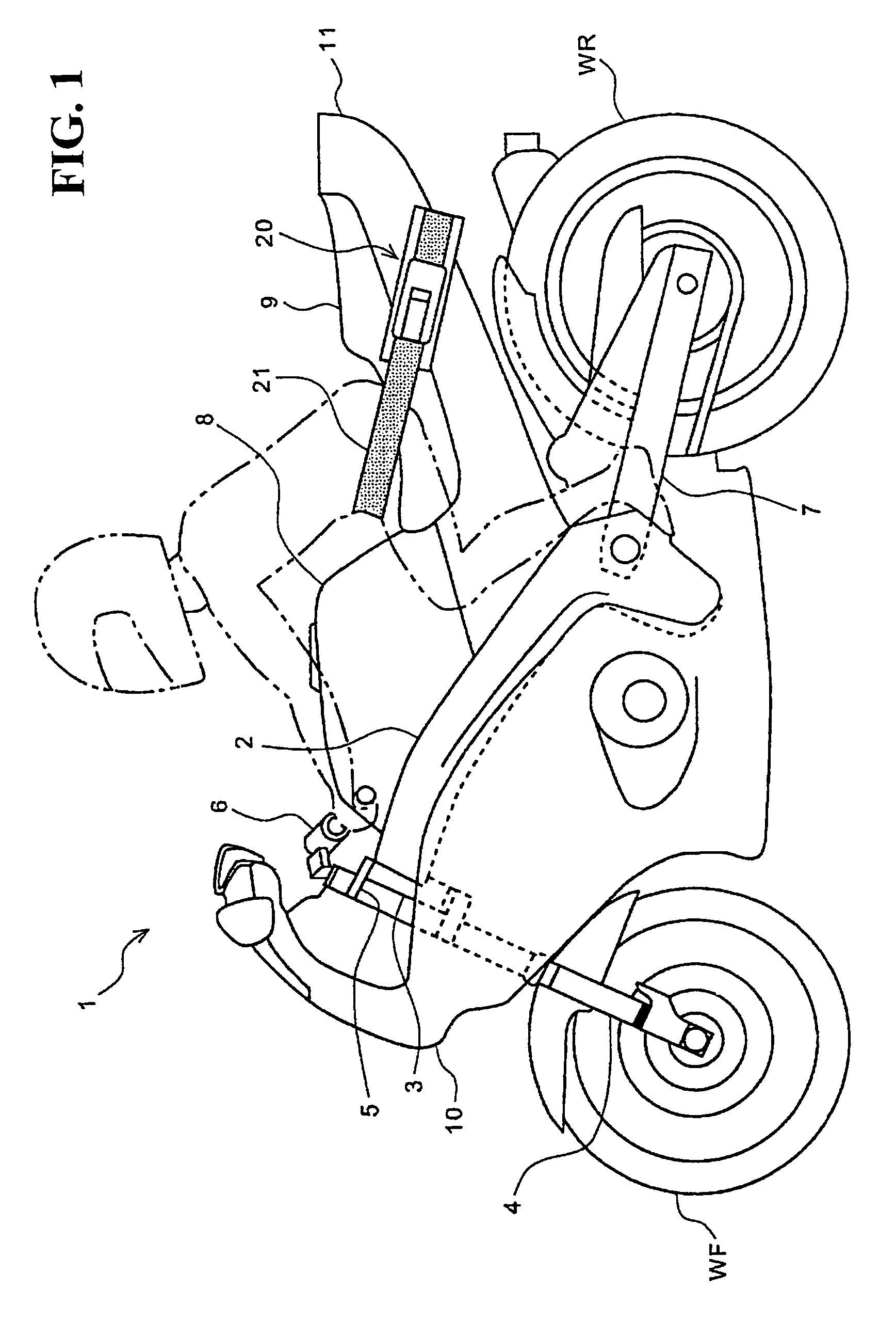
[0031]Hereinafter, a description is given of a preferred embodiment of the present invention in detail with reference to drawings. FIG. 1 is a side view of an embodiment of a two-wheeled vehicle to which the present invention is applied.

[0032]A head pipe 3 is attached to a front end of a body frame 2 of a two-wheeled vehicle 1. A front fork 4, which pivotally supports a front wheel WF, is steerably attached to the head pipe 3. A steering handle 6 is attached to a top ridge 5 provided in an upper portion of the front fork 4. At a lower rear portion of the vehicle frame 2, a swing arm 7 is pivotally supported so as to swing up and down. At a rear end of the swing arm 7, a rear wheel WR is pivotally supported. In an upper front half of the body flame 2, a fuel tank 8 is disposed. At the rear of the fuel tank 8, a seat 9 on which a rider sits is provided. Most of the two-wheeled vehicle 1 is covered with a body cover composed of a front cowl 10 and a rear cowl 11. A collision detection ...


PUM


Abstract

To provide rider restraint means capable of allowing a rider to freely leave a vehicle without a manual release operation when there is no need to restrain the rider to the vehicle. The rider restraint means includes a belt restraining a rider, buckles making the belt detachable, a guide rail making the buckles slidable, a retractor unit controlling the slide of the buckles, and coupling release means releasing coupling between the belt and the buckles in conjunction with the slide of the buckles. The coupling release means includes an inner wire, a wire stopper, and a wire end. The coupling release means releases the coupling between the belt and the buckles when the retractor unit loosens the winding after collision and the buckles slide by a predetermined distance or more or when the rider continues to pull the belt in a state other than collision and the buckles slide by a predetermined distance or more.

Description

CROSS-REFERENCE TO RELATED APPLICATIONS[0001]This nonprovisional application claims priority under 35 U.S.C. § 119(a) on Patent Application No. 2004-284909, filed in Japan on Sep. 29, 2004, the entirety of which is incorporated herein by reference.BACKGROUND OF THE INVENTION[0002]1. Field of the Invention[0003]The present invention relates to a rider restraint apparatus. In particular, the present invention relates to a rider restraint apparatus, which is suitable for a small vehicle and is capable of allowing a rider to leave the vehicle freely when there is no need to restrain the rider on the vehicle.[0004]2. Description of Background Art[0005]A rider restraint apparatus of a small vehicle has been hitherto known in the background art. The rider restraint apparatus according to the background art includes an airbag that absorbs impact which the rider is subjected to when the vehicle crashes and a seat belt that prevents the rider from leaving forward to enhance the effect of the ...

Claims


Application Information

Patent Timeline
Patent Type & Authority Patents(United States)
IPC IPC(8): B60R22/06
CPCB60R22/322B62J27/00B60R22/4676B60R2021/0088B60R2022/3424B62J27/10
Inventor MATSUO, HISASHI
Owner HONDA MOTOR CO LTD
Why Eureka
Try Eureka