Storage cabinet with locking system having dual release members

a locking system and storage cabinet technology, applied in the field of storage cabinets, can solve the problems of inconvenient opening of the cabinet when an operator's hands are full, performance issues of current latching systems, and difficulty in closing and latching the doors, so as to reduce the tendency of the bolster

Inactive Publication Date: 2008-05-13
APEX BRANDS
View PDF27 Cites 21 Cited by
  • Summary
  • Abstract
  • Description
  • Claims
  • Application Information

AI Technical Summary

Benefits of technology

[0009]A preferred embodiment of the storage cabinet includes two doors, each of which includes a front panel that is forwardly spaced from said support member, and the upper and lower release members are of a length such that they do not protrude forwardly beyond the front panels of the doors. This protects passers-by from snagging clothing on the release levers.
[0010]In another embodiment, a storage cavity of the present invention includes a container, a support member and at least one door as defined above, and further includes a latching mechanism having at least one release member protruding forwardly from the support member and being movable from a latched position, in which the latching mechanism latches the door in the closed position, and an unlatched position, in which the latching mechanism allows the door to move to the open position. The latching mechanism also includes a generally vertically disposed post that is slidably mounted on the support member for vertical movement relative thereto. The post is attached to the at least one release member. The latching mechanism further includes a biasing unit (for example, a spring) that biases the latching mechanism toward the latched position. This configuration enables the latching mechanism to move from the unlatched position to the latched position without the operator actively causing this action. This feature can assist in keeping one or more doors of the cabinet closed.
[0011]Another aspect of the present invention is a bolster assembly that can be used with storage cabinets of the type described above. Such a bolster assembly includes: a lower channel having a horizontally-disposed floor and opposed upright side walls; a front bracket having a horizontally-disposed floor and an upright front wall, wherein the front bracket floor is attached to and overlies a front portion of the lower channel floor; a rear bracket having a horizontally-disposed floor and an upright rear wall, wherein the rear bracket floor is attached to and overlies a rear portion of the lower channel floor; a front castor attached to and underlying the front portion of said lower channel; and a rear castor attached to and underlying the rear portion of said lower channel. A bolster assembly of this configuration can provides a reinforced mounting location for the casters that reduces the tendency of the bolster to fail under load.

Problems solved by technology

One difficulty with the latching and locking mechanisms of current storage cabinets is the inconvenience of opening the cabinet when an operator's hands are full.
Another performance issue of current latching systems presents itself when the operator wishes to close the doors.
If the operator reaches in to gather items from within the cabinet and has his hands full, closing and latching the doors is difficult, because the latch remains in the unlatched position until actively moved back by the operator.
A related problem occurs when the operator wishes to open only one door; with the latching mechanism in the unlatched position, the door that he wishes to remain closed will have a tendency to open unless he actively moves the release lever back to the locking position after opening the door he wishes to open.
Another shortening of the current cabinets is the tendency of the bolsters to fracture when casters are mounted thereunder.
The cabinets are often loaded sufficiently that bolsters of this structure may have inadequate strength to support the load; as a result, the bolsters fail at the mounting locations of the casters.

Method used


Image

  • Storage cabinet with locking system having dual release members
  • Storage cabinet with locking system having dual release members
  • Storage cabinet with locking system having dual release members

Examples


Embodiment Construction

[0022]The present invention now will be described more fully hereinafter with reference to the accompanying drawings, in which preferred embodiments of the invention are shown and described. This invention may, however, be embodied in many different forms and should not be construed as limited to the embodiments set forth herein; rather, these embodiments are provided so that this disclosure will be thorough and complete, and will fully convey the scope of the invention to those skilled in the art. Like numbers refer to like components throughout. Some layers, thicknesses, and other dimensions may be exaggerated for clarity.

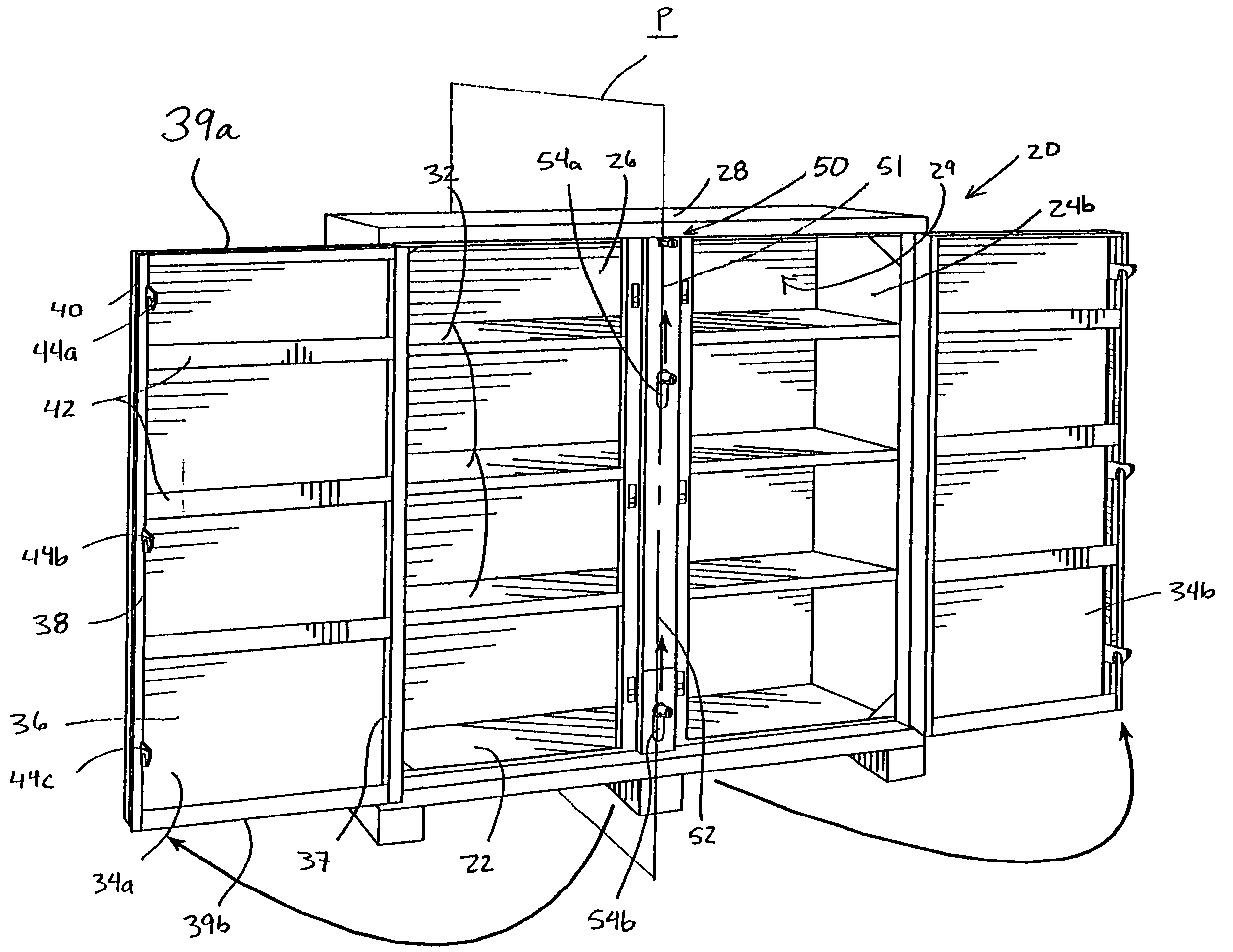
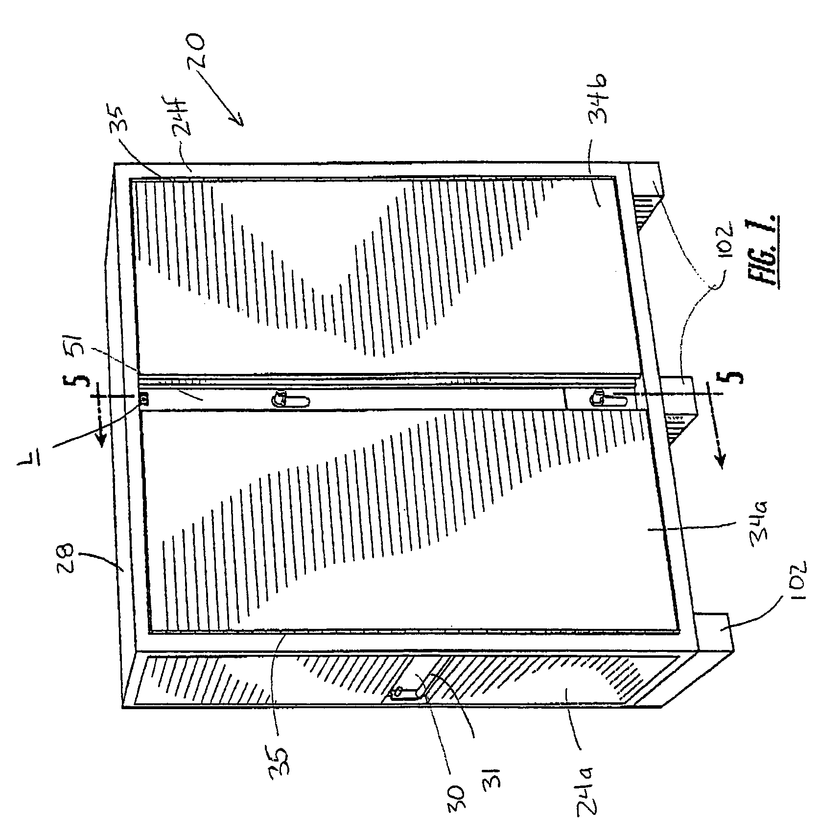
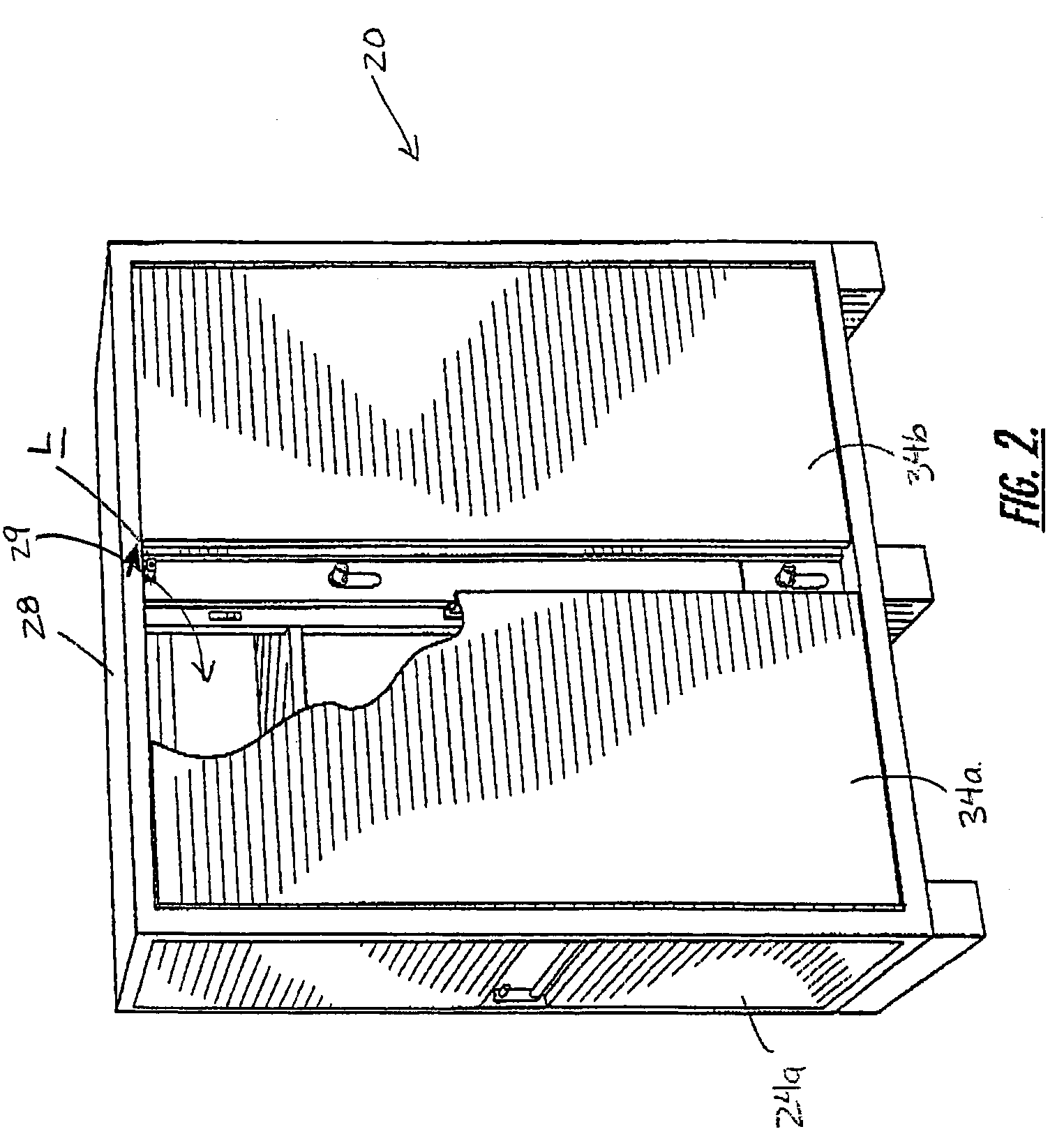
[0023]Turning now to the drawings, a storage cabinet, designated broadly at 20, is illustrated in FIGS. 1-4. The cabinet 20 includes a generally horizontal floor 22 supported by three bolsters 102, two side walls 24a, 24b that rise vertically from opposite lateral edges of the floor 22, a rear wall 26 that rises vertically from the rear edge of the floor 22, and ...


PUM


Abstract

A storage cabinet comprises: a container having a floor, upright side walls and a rear wall attached to and extending upwardly from the floor, and a ceiling attached to the side walls and rear wall, the floor, side walls, rear wall, and ceiling defining a storage cavity; a vertical support member extending upwardly from the floor; at least one door pivotally attached to one of the side walls and movable between an open position, in which the cavity is accessible from a position forward thereof, and a closed position, in which the door contacts the support member and prevents access to the cavity from a position forward thereof; and a latching mechanism attached to the support member. The latching mechanism includes two release members protruding forwardly from the support member, wherein an upper one of the release members is positioned above a lower one of the release members. The release members are movable in unison from a latched position, in which the latching mechanism latches the door in the closed position, and an unlatched position, in which the latching mechanism allows the door to move to the open position. In this configuration, an operator carrying a load with both hands can choose to unlatch the door by hand or by foot, depending on which method is more convenient.

Description

FIELD OF THE INVENTION [0001]The present invention is directed generally to storage cabinets, and more particularly to locking systems for storage cabinets.BACKGROUND OF THE INVENTION [0002]Large storage cabinets used in the construction industry are often formed of steel sheet. Such cabinets typically include opposed side walls, a rear wall, a floor, a ceiling, and one or two doors that are pivotally mounted on the front edges of the side walls to provide access to the cabinet from the front. The floor, walls and ceiling of the cabinet can be formed either from a single sheet of steel that is bent at intersecting edges of these surfaces or from multiple pieces of sheet steel that are welded together. Often, such a cabinet will also include one or more shelves which facilitate the storage of tools and other items. Also, many cabinets have bolsters underlying the floor, and some will include casters beneath the bolsters. The doors of the cabinet are typically formed of a single sheet...

Claims


Application Information

Patent Timeline
Patent Type & Authority Patents(United States)
IPC IPC(8): E05C1/00E05B53/00E05B63/00E05B65/00E05B65/02E05C9/02
CPCE05B53/001E05B65/025E05C9/02E05B63/0052E05B65/0003Y10T292/0968Y10T292/0836Y10T292/0846Y10T292/696Y10T292/432Y10T292/0807Y10T70/5097
Inventor SAMSEL, RICHARD A.
Owner APEX BRANDS
Why Eureka
Try Eureka