
Pressure-cooking appliance having a single control member for decompression and for locking/unlocking

a technology of control member and pressure cooker, which is applied in the direction of cooking vessels, transportation and packaging, and reusing gathering, etc., can solve the problems of difficult to use, difficult to understand, and difficult to understand the sequence of pressure cookers, so as to achieve simple and intuitive use

Active Publication Date: 2008-05-20
SEB SA
View PDF12 Cites 77 Cited by
  • Summary
  • Abstract
  • Description
  • Claims
  • Application Information

AI Technical Summary

Benefits of technology

The invention is a new household appliance for cooking food under pressure. It has several technical effects. Firstly, it is simple and intuitive to use. Secondly, it is highly ergonomic. Thirdly, it reduces the chance of user errors. Fourthly, it is compact and design is simplified. Fifthly, it is safe and secure. Lastly, it offers a good balance between cooking speed and decompression speed. The appliance consists of a bowl and lid designed to form a leaktight cooking vessel, with locking / unlocking means and decompression means connected to a single control member.

Problems solved by technology

That multiplicity of control members makes known pressure cookers awkward to handle, in particular for a user who is used to cooking with conventional cooking pots that operate at atmospheric pressure.
In addition to it being necessary for the user to memorize that sequence of distinct operations, said sequence is even more restrictive since it forces users of conventional pressure cookers to know the functions of the various control buttons and sliders present on the pressure cooker, which is far from always being easy and intuitive.
In addition, the multiplicity and the diversity of the control members present on a conventional pressure cooker gives rise to mechanical designs that are relatively complex, and that involve numerous moving parts, which can give rise to non-negligible risks of wear and jamming, and to problems of reliability.

Method used


Image

  • Pressure-cooking appliance having a single control member for decompression and for locking/unlocking
  • Pressure-cooking appliance having a single control member for decompression and for locking/unlocking
  • Pressure-cooking appliance having a single control member for decompression and for locking/unlocking

Examples


Embodiment Construction

[0035]The appliance of the invention is designed to cook various kinds of food under pressure in a household context.

[0036]The appliance of the invention is thus a cooking utensil that is portable (i.e. that can be moved by hand) and independent.

[0037]Conventionally, the appliance of the invention is designed to be brought up to pressure exclusively under the effect of a heat source (integrated or external), without external pressure being provided.

[0038]Preferably, the cooking appliance of the invention is a pressure cooker.

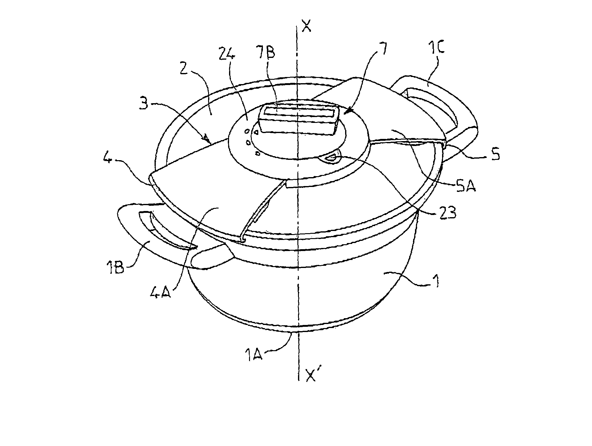
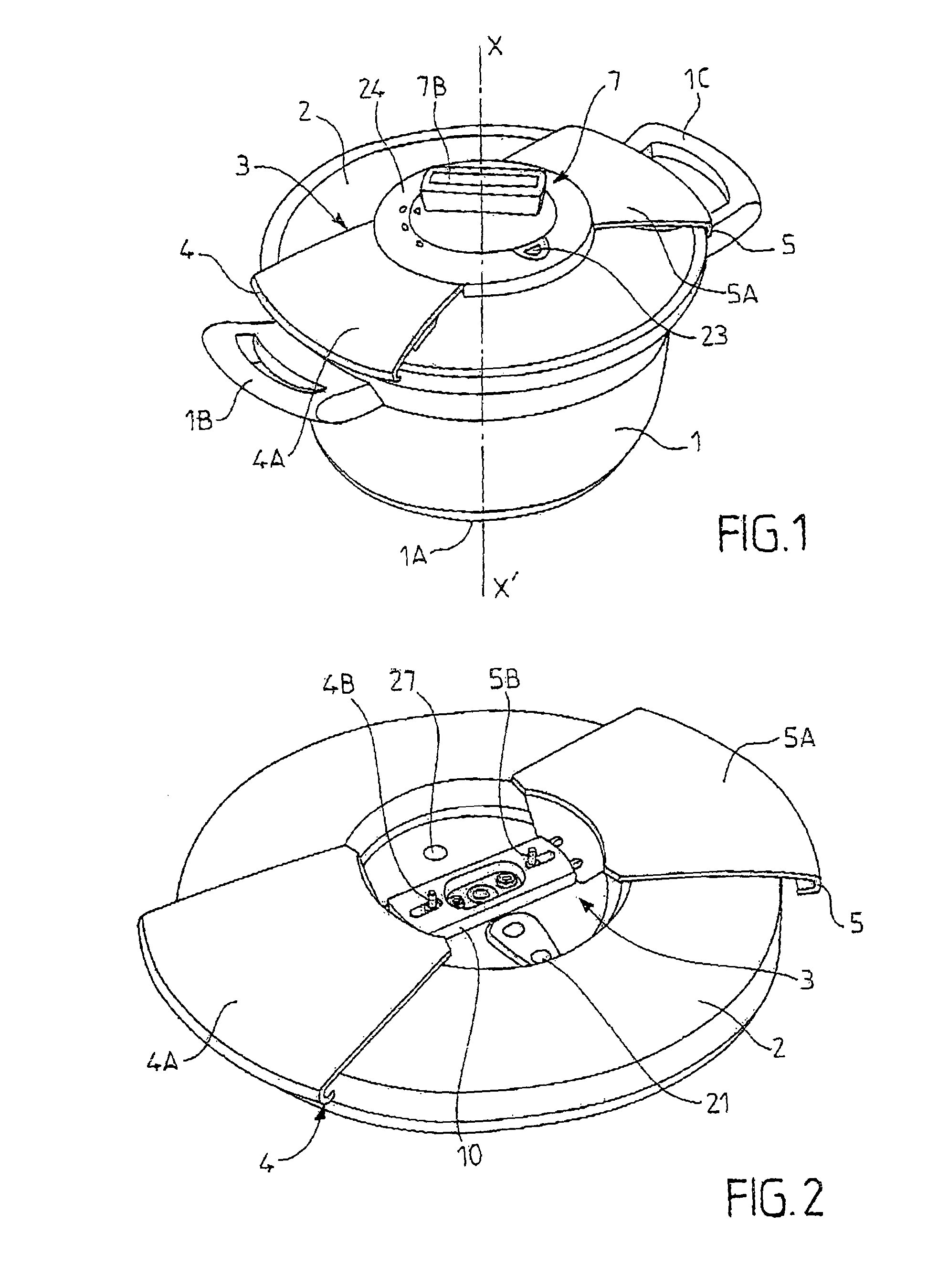
[0039]Conventionally, the cooking appliance of the invention includes a bowl 1 forming a cooking receptacle and preferably being circularly symmetrical about an axis X-X′ (cf. FIG. 1).

[0040]Below, the adjective “axial” refers to the direction of said axis of symmetry X-X′ which is substantially the same as the vertical direction when the appliance is operating normally.

[0041]In conventional manner, the bowl 1 is manufactured from a metal material such as stainle...


PUM


Abstract

The invention relates to an appliance for cooking food under pressure, the appliance comprising:a bowl and a lid;locking / unlocking means suitable for going between a locking position in which the lid (2) is locked relative to the bowl and an unlocking position; anddecompression means (6) for decompressing the vessel;wherein said locking / unlocking means and said decompression means (6) are connected functionally to a single, common control member (7A), said control member (7A) being designed to be suitable for finding itself in a locking and decompression position in which the locking / unlocking means find themselves in their locking position, while the decompression means are activated. The invention is applicable to household appliances for cooking under pressure.

Description

CROSS-REFERENCE TO RELATED APPLICATION[0001]This Application claims priority to copending French Patent Application entitled, “A Pressure-Cooking Appliance Having A Single Control Member For Decompression And For Locking / Unlocking,” having Application No. FR-03 13937, filed on Nov. 27, 2003, which is entirely incorporated herein by reference.[0002]The present invention relates to the general technical field of household appliances for cooking under pressure, such an appliance comprising a bowl and a lid designed to be locked onto the bowl to form a leaktight cooking vessel. Such an appliance serves to cook food contained in the bowl under steam pressure[0003]The present invention relates more particularly to a household appliance for cooking food under pressure, the appliance comprising:[0004]bowl and a lid designed to be mounted on and locked onto said bowl to form a leaktight cooking vessel;[0005]locking / unlocking means having jaws or segments, and suitable for going between a loc...

Claims


Application Information

Patent Timeline
Patent Type & Authority Patents(United States)
IPC IPC(8): A23L1/00A47J27/08A47J27/092
CPCA47J27/0813A47J27/092Y10S220/912
Inventor SEURAT GUIOCHET, CLAIRE MARIE-AUROREANOTA, DANIEL JEAN-MARIECHAMEROY, ERIC
Owner SEB SA
Learn More