
Detachable case assembly for computer server

a computer server and assembly technology, applied in the field of computer servers, can solve the problems of inconvenient design and complicating maintenance work, and achieve the effect of stabilizing the detachable case assembly

Inactive Publication Date: 2008-05-20
TATUNG COMPANY
View PDF8 Cites 25 Cited by
  • Summary
  • Abstract
  • Description
  • Claims
  • Application Information

AI Technical Summary

Benefits of technology

[0007]The present invention has been accomplished under the circumstances in view. It is therefore the main object of the present invention to provide a detachable case assembly for computer server, which enables the user to detach the front or rear cover separately to facilitate maintenance work. It is another object of the present invention to provide a detachable case assembly for computer server, which is easy to install and can maintain the stability of the structure with the use of a limited number of screws.
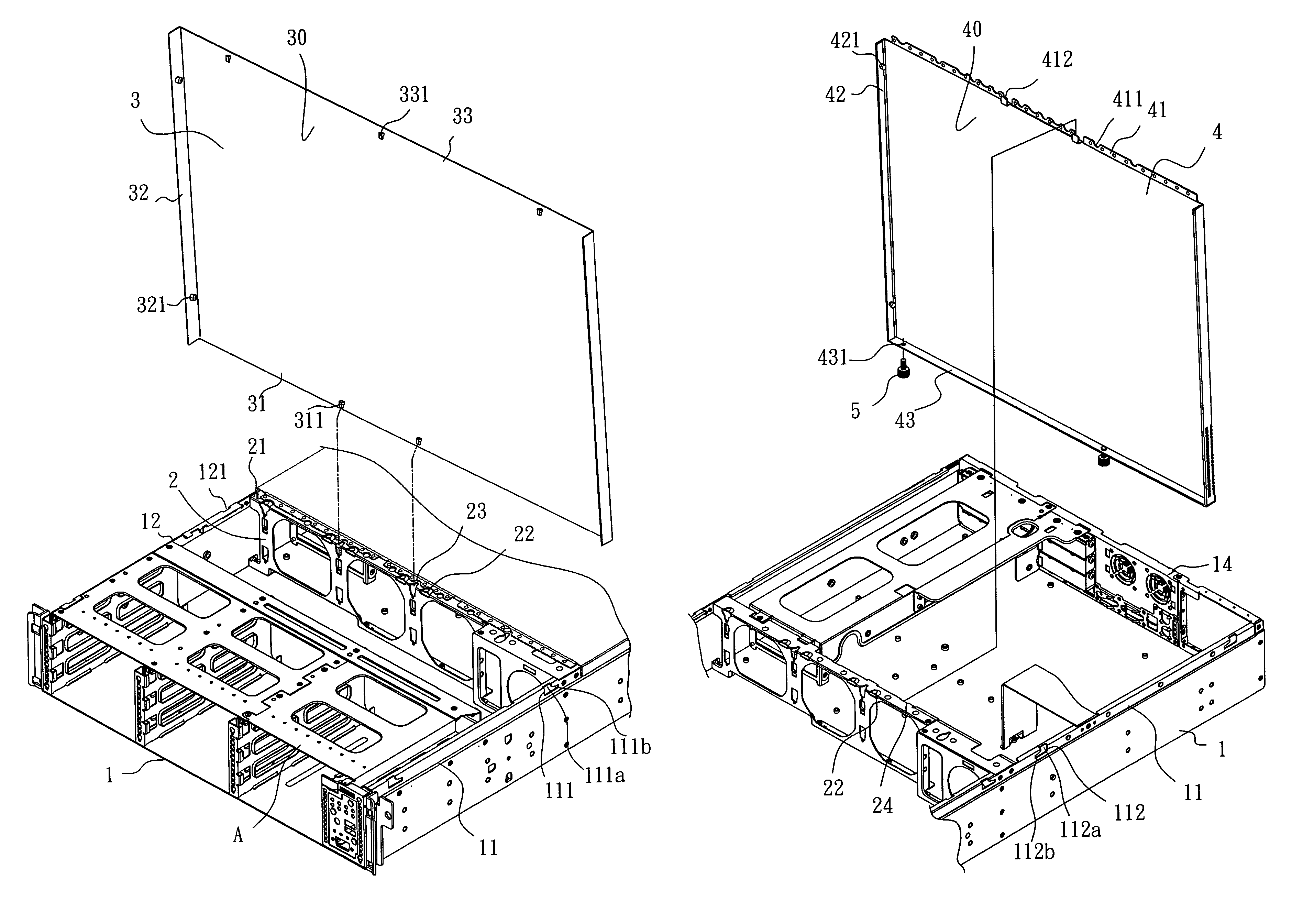
[0009]In addition, the front cover and the rear cover are respectively covered on the front and rear part of the top side of the case body; the rear edge of the front cover and the front flange of the rear cover are suspended above the top flange of the partition plate at different elevations; the rear edge of the front cover is supported on the bearing portions of the partition plate and spaced by the bearing portions above the top flange of the partition plate and the front flange of the rear cover. Therefore, the front cover and the rear cover can be separately and rapidly mounted on or dismounted from the case body of the detachable case assembly, and the desired stability of the detachable case assembly can be achieved simply by using two screws.

Problems solved by technology

However, the front and rear covers of a conventional computer server are not separately detachable, i.e., both the front and rear covers must be removed from the case of the computer server when wishing to repair component parts in the front or rear part of the inside space of the computer server's case.
This inconvenience design complicates maintenance work.

Method used


Image

  • Detachable case assembly for computer server
  • Detachable case assembly for computer server
  • Detachable case assembly for computer server

Examples


Embodiment Construction

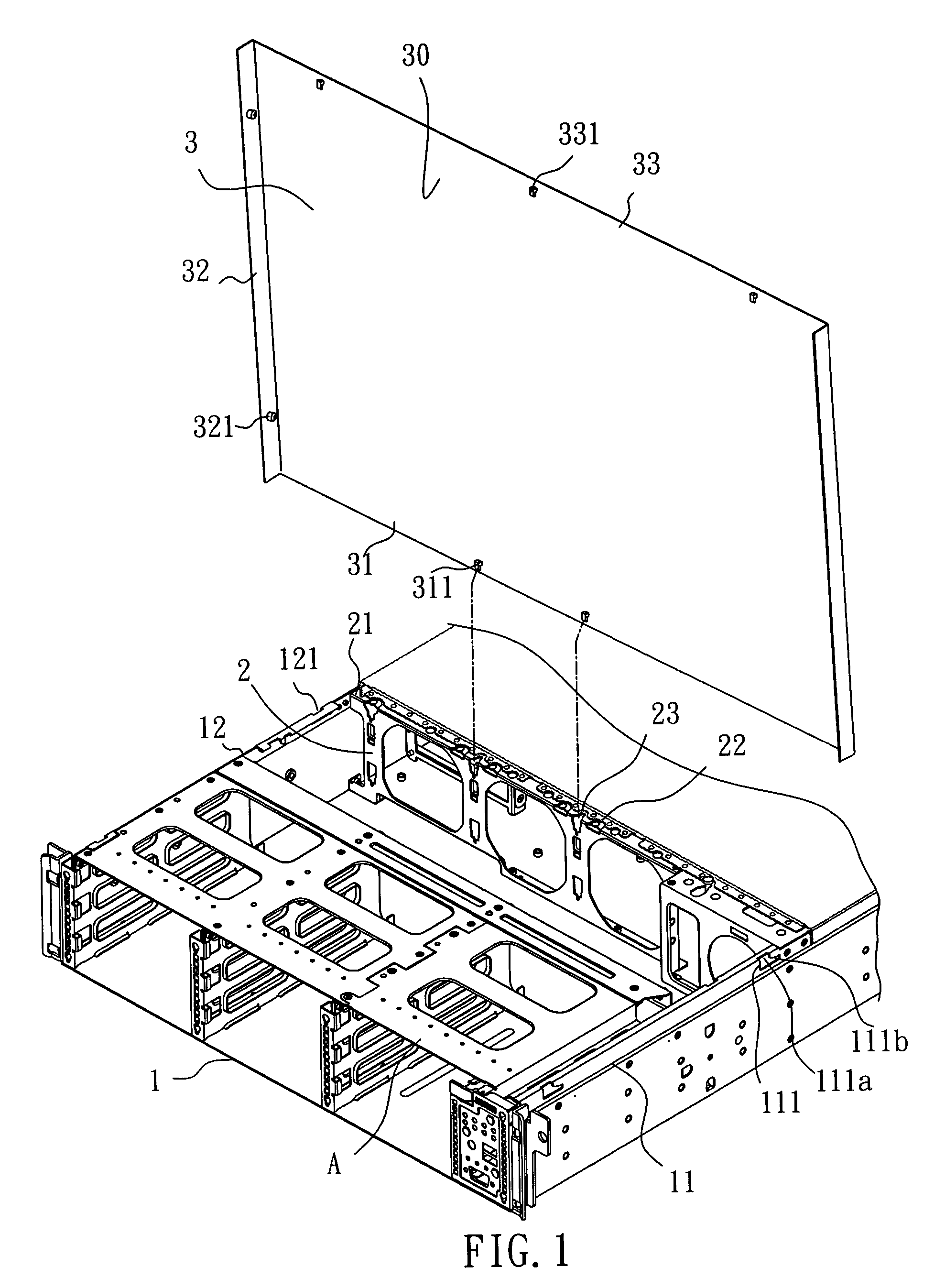
[0015]Referring to FIG. 1, a detachable case assembly for computer server in accordance with the present invention is shown comprised of a case body 1, a partition plate 2, and a front cover 3.

[0016]The case body 1 comprises a top panel 13, two side panels 11 and 12, and a back panel 14 (not shown; see FIG. 3). The top panel 13 covers the top side of the front part of the case body 1. The two side panels 11 and 12 each have two angled slots 111 or 121 at the respective front half. Each angled slot 111 or 121 comprises a vertical slot portion 111a and a horizontal slot portion 111b perpendicularly backwardly extended from the bottom end of the vertical slot portion 111a.

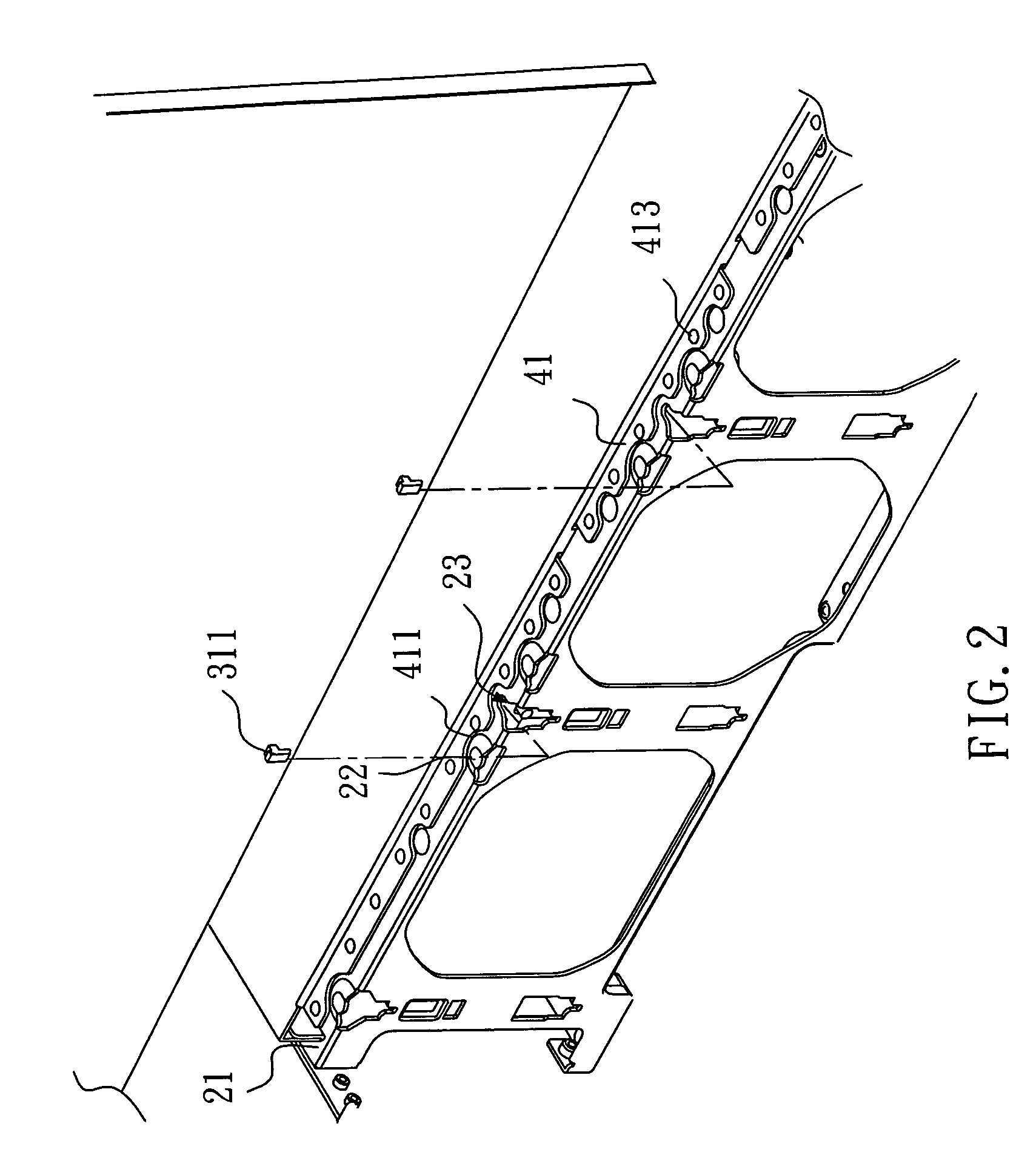
[0017]The partition plate 2 is transversely mounted inside the case body 1 on the middle, having a top mounting flange 21. The top mounting flange 21 has a plurality of bearing portions 22 protruding over the top surface, a plurality of recessed retaining portions 23, and two plugholes 24 (not shown; see FIG. 3).

[001...


PUM


Abstract

A detachable case assembly is disclosed to include a case body, which has front and rear angled slots, a partition plate, which separates the case body into a front and a rear holding space, a front cover, which covers the front half of the top side of the case body and which has locating rods for engaging into the front angled slots of the case body and a rear edge supported on the protruded bearing portions of the partition plate, and a rear cover, which covers the rear half of the top side of the case body and which has locating rods for engaging into the rear angled slots of the case body, a front flange supported on the partition plate and spaced below the rear edge of the front cover, raised contact portions maintained in close contact with the rear edge of the front cover.

Description

BACKGROUND OF THE INVENTION[0001]1. Field of the Invention[0002]The present invention relates to a computer server and more particularly, to a detachable case assembly for computer server, which comprises a front cover and a rear cover respectively detachably covered on the front and rear halves of the top side of the case body thereof.[0003]2. Description of Related Art[0004]Different firms for the advantage of standardized machine size convenient for management in a machine room to fully utilize the limited floor space of the machine room popularly accept computer servers.[0005]A regular computer server has many parts on the inside and a big horizontal area. Conventional computer servers commonly have two covers, namely, the front cover and the rear cover that have the outer part of the computer server well packed and maintain sufficient rigidity of the case.[0006]However, the front and rear covers of a conventional computer server are not separately detachable, i.e., both the fro...

Claims


Application Information

Patent Timeline
Patent Type & Authority Patents(United States)
IPC IPC(8): G06F1/16G06F1/18H05K5/00H05K5/04H05K9/00
CPCG06F1/181H05K5/0013H05K9/0073
Inventor WU, CHIA-KANGLIANG, YU-JENHSUI, FU-JUNG
Owner TATUNG COMPANY
Learn More