
Diagnostic test strip for collecting and detecting an analyte in a fluid sample

a technology of fluid sample and diagnostic test, applied in the field of diagnostic instruments, can solve the problems of insufficient sample collection for accurate analysis, difficult positioning of collection instruments for proper collection, and further compounding of problems

Active Publication Date: 2008-05-20
ASCENSIA DIABETES CARE HLDG AG
View PDF21 Cites 140 Cited by
  • Summary
  • Abstract
  • Description
  • Claims
  • Application Information

AI Technical Summary

Problems solved by technology

A drawback associated with the use of physically separate lancing and collection devices is that a patient / user must manipulate two different instruments requiring the user / patient to bring the collection device (e.g., the test strip) to the area of skin that has been lanced to collect the sample.
In other situations, not enough sample is collected for accurate analysis because the collection device is not properly positioned.
This problem can be further compounded if the user has impaired vision or poor dexterity.
Because test systems are requiring smaller volumes of blood for analysis, it is difficult to position a collection instrument for proper collection.
Many individuals use hand lotions, have oily or sweaty skin, or do not dry their hands completely after washing which also affects droplet formation.
Often users do not always cleanse the area of skin to be lanced with alcohol.
These variations increase the wettability of the skin's surface causing the droplet to spread in an uncontrolled and unpredictable manner making it difficult to harvest the sample.
Further, the collection of blood samples on alternative sites such as the forearm is complicated by the presence of body hair because the sample (e.g., blood) has a tendency to “wick up” the hairs found on these parts of the body.
Cleaning the lance site with alcohol does not alleviate this wicking problem.

Method used


Image

  • Diagnostic test strip for collecting and detecting an analyte in a fluid sample
  • Diagnostic test strip for collecting and detecting an analyte in a fluid sample
  • Diagnostic test strip for collecting and detecting an analyte in a fluid sample

Examples


Embodiment Construction

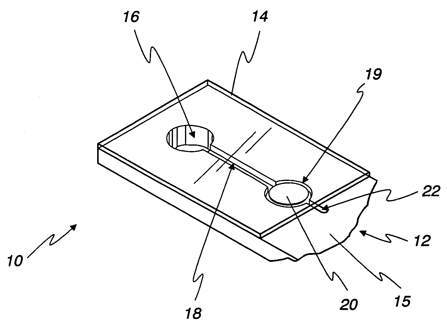
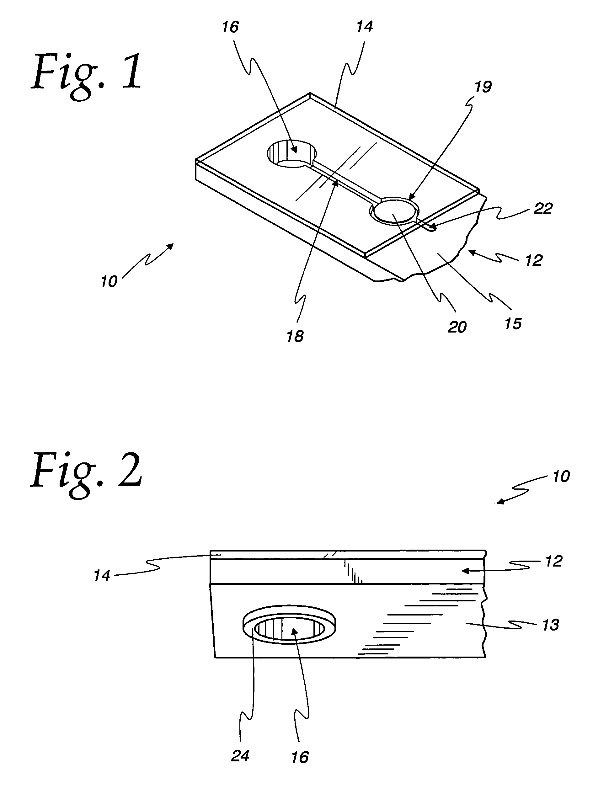
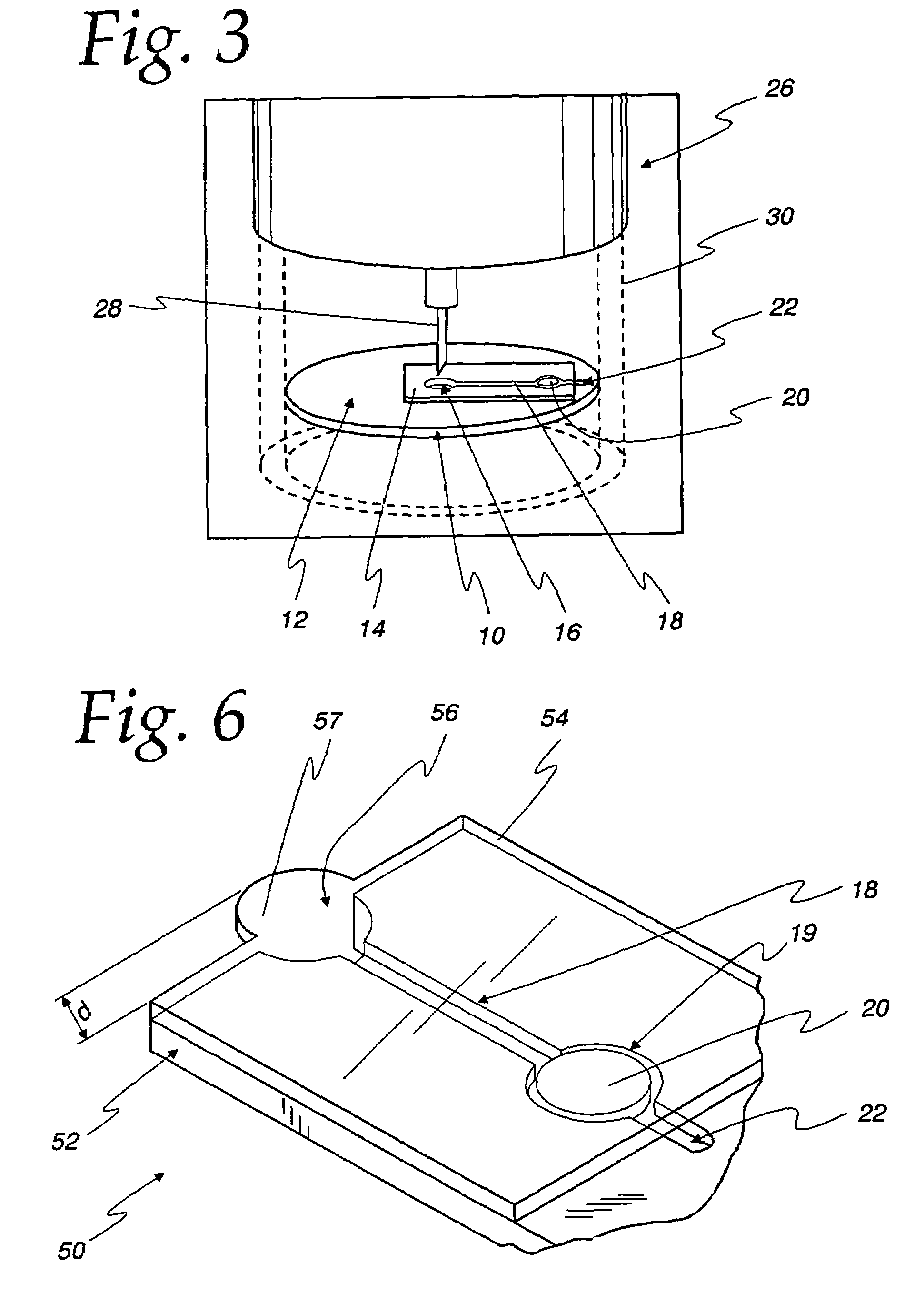
[0016]Turning now to the drawings and initially to FIGS. 1 and 2, a test strip 10 is shown according to one embodiment of the present invention. The test strip 10 includes a base 12 and a lid 14. The base 12 has a lower surface 13 and an upper surface 15. The base 12 includes a collection chamber 16, a capillary channel 18 that includes a test area 19, and a containing ring 24. The capillary channel 18 is extended beyond the test area 19 to form an optional vent 22. The lid 14 covers the collection chamber 16 and the capillary channel 18 including the test area 19. The lid 14 is adhered to the base 12 according to one embodiment of the present invention. A test element 20, which includes a regent for use in an assay, is disposed in the test area of the capillary channel 18. The test strip 10 may be incorporated into a lancing and harvesting device 26 (FIG. 4) according to one embodiment of the present invention as will be described in detail in connection with FIGS. 4-5f.

[0017]The ...


PUM

PropertyMeasurementUnit
areaaaaaaaaaaa
concentrationaaaaaaaaaa
hydrophilicaaaaaaaaaa

Abstract

A test strip for the use of the determination of an analyte in a fluid sample according to one embodiment of the present invention is disclosed. The test strip comprises of a base having a top and a bottom, a collection chamber that extends between the top and the bottom of the base, a containing ring that is disposed on the bottom of the base and surrounds the collection chamber, and a capillary channel formed in top of the base that has an inlet fluidly coupled to the collection chamber and a test element disposed within the capillary channel. A lid is attached to the top of the base and covers the collection chamber, the test area, and at least a portion of the capillary channel.

Description

[0001]This application claims benefit of U.S. Provisional Application Ser. No. 60 / 473,720 filed on May 29, 2003.FIELD OF THE INVENTION[0002]The present invention relates generally to diagnostic instruments and, more particularly, to a diagnostic test strip for use in determining the concentration of an analyte in a liquid sample.BACKGROUND OF THE INVENTION[0003]Test strips (e.g., biosensors) containing reagents are often used in assays for determining the concentration of an analyte in a fluid sample. Testing and self-testing for the concentration of glucose in blood is a common use for test strips. One method of obtaining a blood sample and analyzing the sample for determining the glucose level is with a lancing device and a separate blood collection device. In obtaining a blood sample, a drop of blood is obtained from the fingertip using the lancing device, and the blood is harvested using a test strip, which is then analyzed by a test unit that determines the concentration of glu...

Claims


Application Information

Patent Timeline
Patent Type & Authority Patents(United States)
IPC IPC(8): A61B5/145A61B5/00G01N33/66A61B5/15A61B5/151A61B5/157G01N27/28G01N27/416
CPCA61B5/1411A61B5/14532A61B5/1468A61B5/417A61B5/157Y10T436/25A61B2562/0295Y10T436/2575A61B5/150022A61B5/150099A61B5/150213A61B5/150358A61B5/150412A61B5/15113A61B5/15117A61B5/1519A61B5/15192
Inventor KURIGER, REX J.
Owner ASCENSIA DIABETES CARE HLDG AG
Learn More