
Two stage transformer coupling for ultra-sensitive silicon sensor pixel

a technology of ultra-sensitive silicon and transformer, which is applied in the direction of optical radiation measurement, superconductor devices, instruments, etc., can solve the problems of difficult extension of these devices to other spectral bands, and achieve the effect of significantly more robust mechanical structure, improved inductive coupling between micro-antenna and detector stage, and minimizing overhang

Active Publication Date: 2008-05-20
NORTHROP GRUMMAN SYST CORP
View PDF3 Cites 14 Cited by
  • Summary
  • Abstract
  • Description
  • Claims
  • Application Information

AI Technical Summary

Benefits of technology

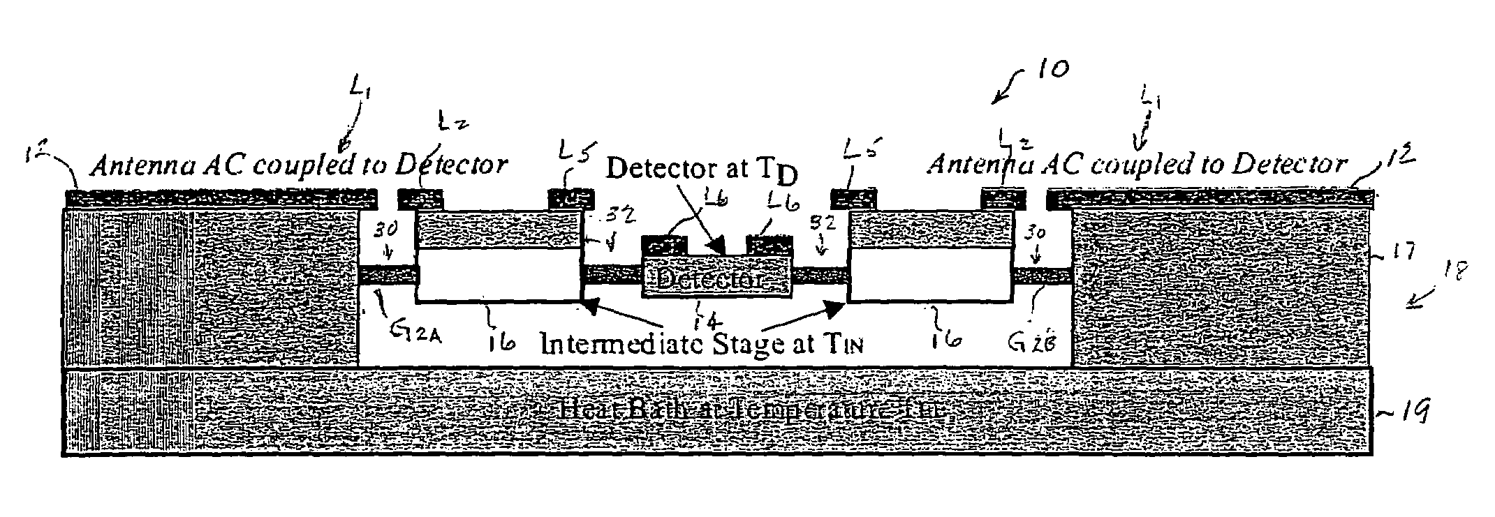
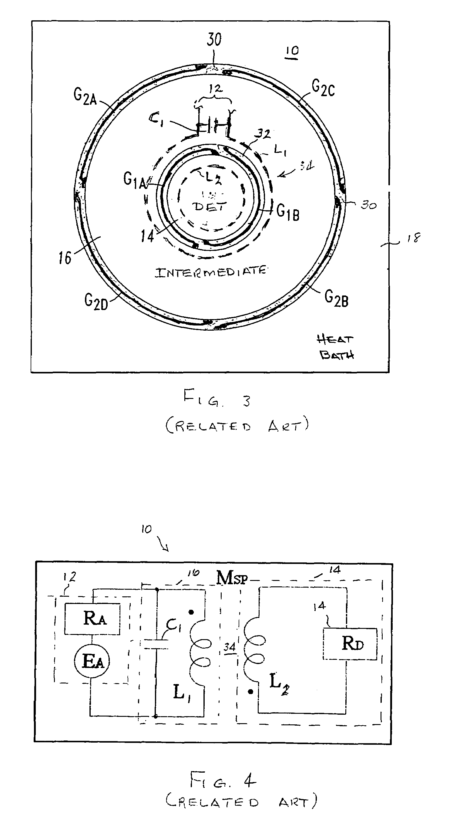
[0009]It is an object of the present invention to provide improvement in a bolometer type ultra-sensitive silicon sensor pixel of a multi-pixel sensor including a detector stage, an intermediate stage, and a heat bath stage. The detector stage, the intermediate stage and a portion of the heat bath stage are generally co-planar and are interconnected by I-beam bridges so as to permit mutually co-planar rotation to accommodate stress or strain. Inductive coupling between a micro-antenna and the detector stage is improved by inductive coupling between the micro-antenna and the detector stage utilizing a two stage transformer assembly. The two stage transformer assembly is made up of a primary transformer stage, an intermediary transformer stage, and a secondary transformer stage. The primary transformer stage is integrated with the micro-antenna. The intermediate transformer stage is integrated mechanically with the intermediate stage. The secondary transformer stage is integrated mechanically with the detector stage. The intermediate transformer stage has two windings, one is located near the primary transformer stage windings and a second winding is located near the detector stage transformer winding. The two windings in the intermediate stage transformer are interconnected by two small inductances. Two resonance capacitors are used, one is located in the primary transformer stage, and the other one is located on the intermediate transformer stage. The two transformer stage design minimizes overhang found in a single transformer stage design. Minimizing the micro-antenna overhang with a two stage transformer leads to a significantly more robust mechanical structure.

Problems solved by technology

Extending these devices to other spectral bands has proven relatively difficult in the past.

Method used


Image

  • Two stage transformer coupling for ultra-sensitive silicon sensor pixel
  • Two stage transformer coupling for ultra-sensitive silicon sensor pixel
  • Two stage transformer coupling for ultra-sensitive silicon sensor pixel

Examples


Embodiment Construction

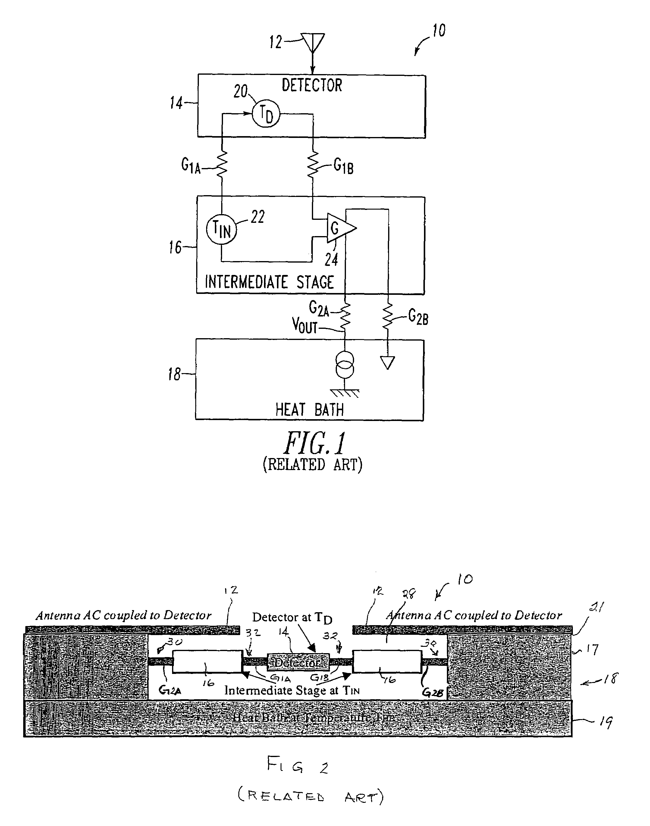
[0024]Referring now to the drawings, wherein like reference characters refer to like components, and more particularly to FIG. 1, shown thereat is an embodiment of an ultra-sensitive silicon sensor pixel 10 including active thermal isolation as disclosed in the above referenced related U.S. Pat. No. 6,489,615. The sensor pixel 10 receives incident thermal type electromagnetic energy directly by means of an antenna 12 and includes three major stages; a detector stage 14, an intermediate stage 16, and a heat bath stage 18. Two temperature sensors 20 and 22 are respectively located intermediate the detector stage and the intermediate stage 16 and comprise a pair of semiconductor diodes connected in back-to-back relationship to an amplifier 24, also located in the intermediate stage 16. The amplifier 24 generates heat in an electro-thermal feedback loop that in combination with the heat bath cooling zeroes the difference in temperature between the temperature TD in the detector stage 14...


PUM


Abstract

A bolometer type ultra-sensitive silicon sensor pixel of a multi-pixel sensor wherein each pixel includes a detector stage, an intermediate stage, and a heat bath stage. The detector stage, the intermediate stage and a portion of the heat bath stage are generally co-planar and are interconnected by I-beam bridges so as to permit mutually co-planar rotation in response to stress and strain. Electrical coupling is improved between a micro-antenna and the detector stage by a two stage transformer assembly that couples the micro-antenna to the detector stage.

Description

GOVERNMENT INTEREST[0001]The U.S. Government has an interest in the subject invention pursuant to Contract No. W911QX-04-C-O0117 from the U.S. Army RDECOM ACQ Center.CROSS REFERENCE TO RELATED APPLICATIONS[0002]This application is related to Non-provisional application Ser. No. 11 / 239,275, Publication No. 2006-0076493 A1 entitled “Focal Plane Antenna to Sensor Interface For An Ultra-Sensitive Silicon Sensor”, filed on Sep. 30, 2005; Non-provisional application Ser. No. 11 / 239,297, Publication No. 2006-0081780 A1 entitled “Ultra-Sensitive Silicon Sensor Readout Circuitry”, filed on Sep. 30, 2005; Non-provisional application Ser. No. 11 / 240,772, Publication No. 2006-0081781 A1 entitled “Sensitive Silicon Sensor and Test Structure for an Ultra-Sensitive Silicon Sensor”, filed on Oct. 3, 2005; and Non-provisional application Ser. No. 11 / 302,229 entitled “‘I’ Beam Bridge Interconnection For Ultra-Sensitive Silicon Sensor”, filed on Dec. 14, 2005.CROSS REFERENCE TO RELATED ART[0003]This a...

Claims


Application Information

Patent Timeline
IPC IPC(8): G01J5/20
CPCG01J5/08G01J5/0837G01J5/24G01J5/20G01J2005/204
Inventor BLUZER, NATHANHARMS, DAVID C.
Owner NORTHROP GRUMMAN SYST CORP
Learn More