Apparatus for moving the effect of a wall switch from its switched power outlet to a non-switched outlet

Inactive Publication Date: 2008-05-20
SMITH MICHAEL GORDON
View PDF7 Cites 36 Cited by
  • Summary
  • Abstract
  • Description
  • Claims
  • Application Information

AI Technical Summary

Benefits of technology

[0011]To attain this, the present invention essentially comprises a controller that can move the effect of a wall switch from its associated switched power outlet socket to any regular (always on) socket by use of a transmitter / receiver paired device located separately in the switched and non-switched power outlets respectively, thus moving the effect of the wall switch without any wiring modifications to the sockets. The invention may use infrared light, ultrasonics, or radio-frequency radiations, or modulations on the power supply within the building such as the X-10 system. The preferred (and prototyped) solution does not require replaceable batteries but instead uses capacitive power storage for use after power has been removed from the transmitter in order to send the “off” signal to the receiver. Both transmitter and receiver use a common capacitive power supply.
[0015]It is therefore an object of the present invention to provide a new and improved apparatus for moving the effect of a wall switch from its switched power outlet to a non-switched outlet which has all of the advantages of the prior art remote control systems and none of the disadvantages.
[0016]It is another object of the present invention to provide a new and improved apparatus for moving the effect of a wall switch from its switched power outlet to a non-switched outlet which may be easily and efficiently manufactured and marketed.
[0017]It is further object of the present invention to provide a new and improved apparatus for moving the effect of a wall switch from its switched power outlet to a non-switched outlet which is of durable and reliable constructions.
[0018]An even further object of the present invention is to provide a new and improved apparatus for moving the effect of a wall switch from its switched power outlet to a non-switched outlet which is susceptible of a low cost of manufacture with regard to both materials and labor, and which accordingly is then susceptible of low prices of sale to the consuming public, thereby making such apparatus economically available to the buying public.

Problems solved by technology

While these devices fulfill their respective, particular objectives and requirements, the aforementioned patents do not describe an apparatus for moving the effect of a wall switch from its switched power outlet to a non-switched outlet.

Method used


Image

  • Apparatus for moving the effect of a wall switch from its switched power outlet to a non-switched outlet
  • Apparatus for moving the effect of a wall switch from its switched power outlet to a non-switched outlet
  • Apparatus for moving the effect of a wall switch from its switched power outlet to a non-switched outlet

Examples


Embodiment Construction

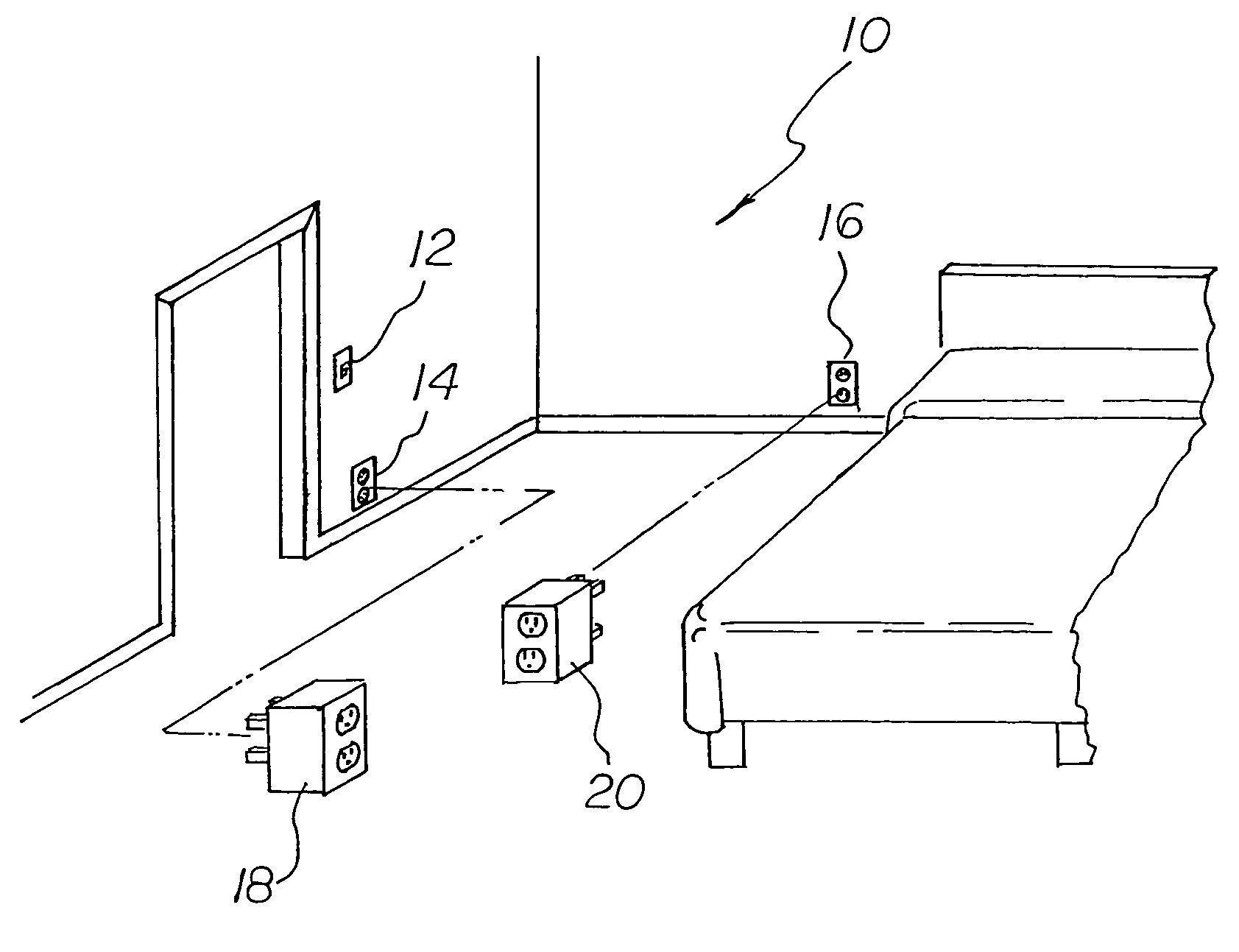
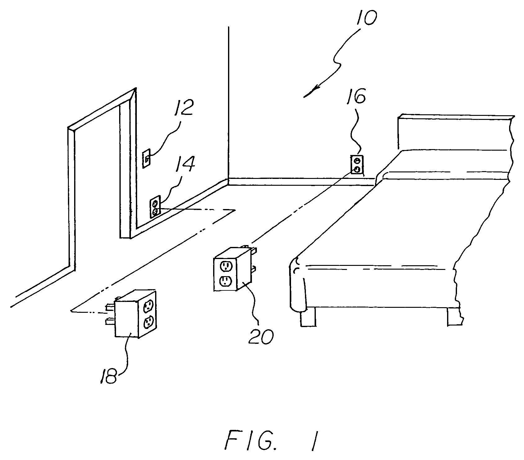
[0027]With reference now to the drawings, and in particular to FIG. 1 thereof, the preferred embodiment of the new and improved apparatus for moving the effect of a wall switch from its switched power outlet to a non-switched outlet embodying the principles and concepts of the present invention and generally designated by the reference numeral 10 will be described.

[0028]The present invention, the apparatus for moving the effect of a wall switch from its switched power outlet to a non-switched outlet 16, is comprised of a plurality of components. Such components in their broadest context include a transmitter and a receiver. Such components are individually configured and correlated with respect to each other so as to attain the desired objective.

[0029]As may be seen in FIG. 1, first provided is an operator controlled wall switch 12. The wall switch is positioned in a room. The wall switch has a first electrical outlet 14. The first electrical outlet is located in the room at a first...


PUM


Abstract

A controller that can move the effect of a wall switch from its associated a controller that can move the effect of a wall switch from its associated switched power outlet socket to any regular (always on) socket by use of a transmitter / receiver paired device located separately in the switched and non-switched power outlets respectively, thus moving the effect of the wall switch without any wiring modifications to the sockets. The invention may use infrared light, ultrasonics, or radio-frequency radiations, or modulations on the power supply within the building such as the X-10 system. The preferred (and prototyped) solution does not require replaceable batteries but instead uses capacitive power storage for use after power has been removed from the transmitter in order to send the “off” signal to the receiver. Both transmitter and receiver use a capacitive power supply.

Description

RELATED APPLICATION[0001]This application is based upon pending Provisional Application No. 60 / 521,431 filed Apr. 24, 2004, the subject matter of which is incorporated herein by reference.BACKGROUND OF THE INVENTION[0002]1. Field of the Invention[0003]The present invention relates to an apparatus for moving the effect of a wall switch from its switched power outlet to a non-switched outlet and more particularly pertains to allowing a user to control a non-switched wall outlet with a switch. In this invention the control is plugged into existing wall electrical outlets and requires no construction or alteration of existing structures.[0004]2. Description of the Prior Art[0005]The use of remote control systems is known in the prior art. More specifically, remote control systems previously devised and utilized for the purpose of controlling systems from remote locations are known to consist basically of familiar, expected, and obvious structural configurations, notwithstanding the myri...

Claims


Application Information

Patent Timeline
Patent Type & Authority Patents(United States)
IPC IPC(8): H01H35/00
CPCH01R13/7038H02J13/0017Y02B90/226Y02B90/2607Y04S20/16Y04S40/12H02J13/0005H02J13/00006Y02B90/20Y04S20/00
Inventor SMITH, MICHAEL GORDON
Owner SMITH MICHAEL GORDON
Why Eureka
Try Eureka