
Color filter and in plane switching type liquid crystal display using the same

a liquid crystal display and color filter technology, applied in non-linear optics, instruments, optics, etc., can solve the problem of narrow viewing angle of lcd, and achieve good display characteristics

Inactive Publication Date: 2008-05-20
INNOLUX CORP
View PDF2 Cites 8 Cited by
  • Summary
  • Abstract
  • Description
  • Claims
  • Application Information

AI Technical Summary

Benefits of technology

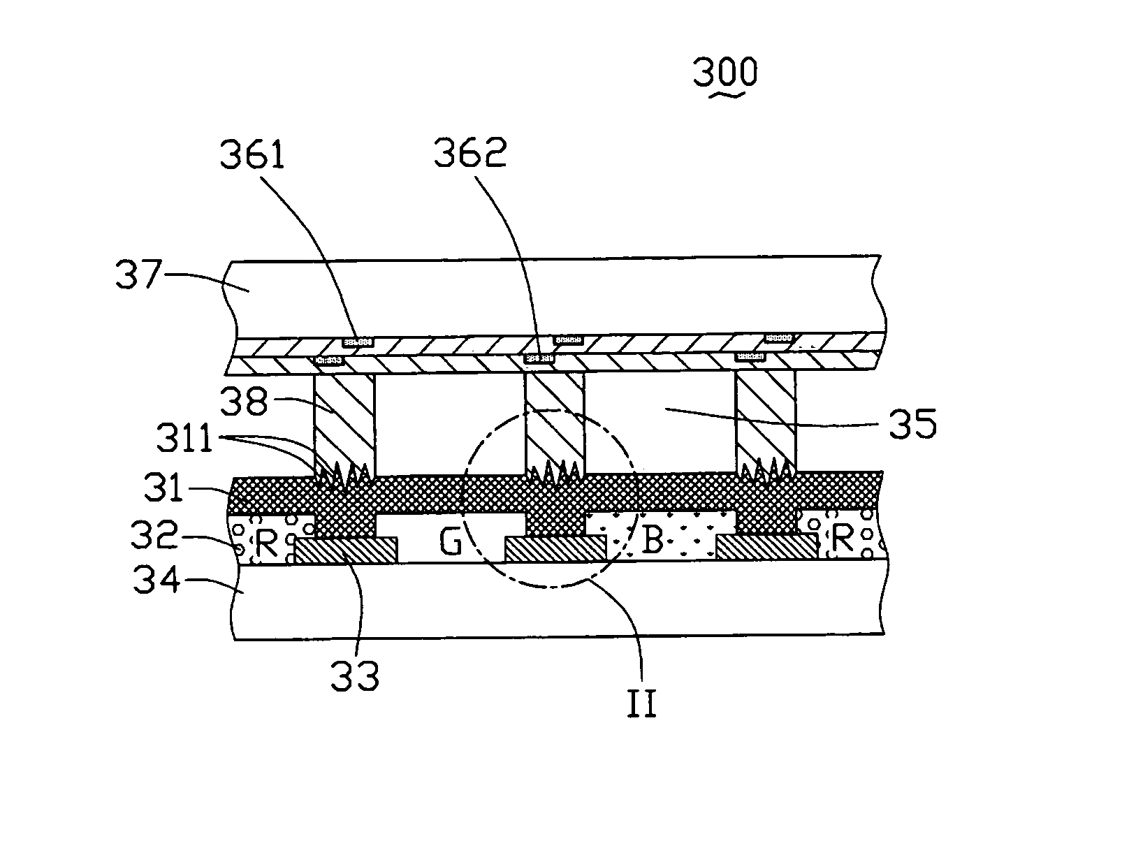
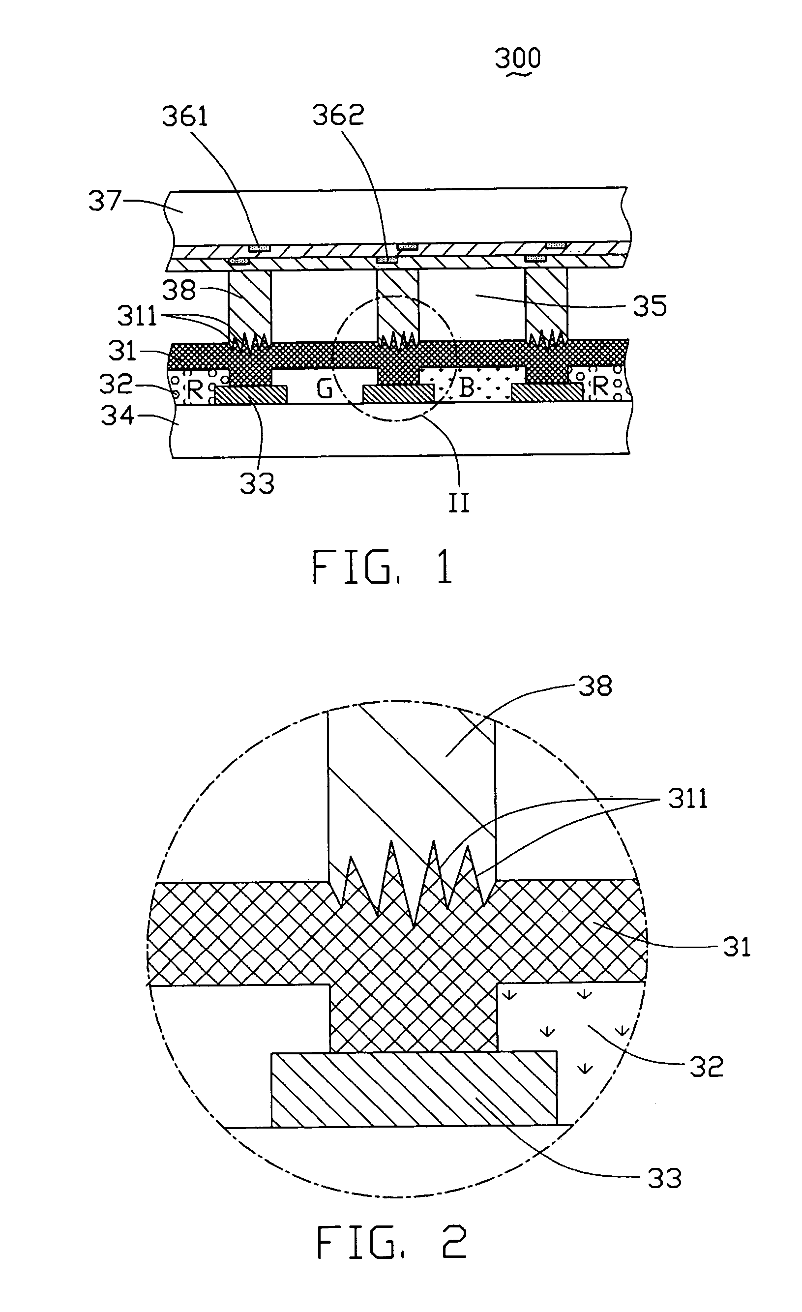
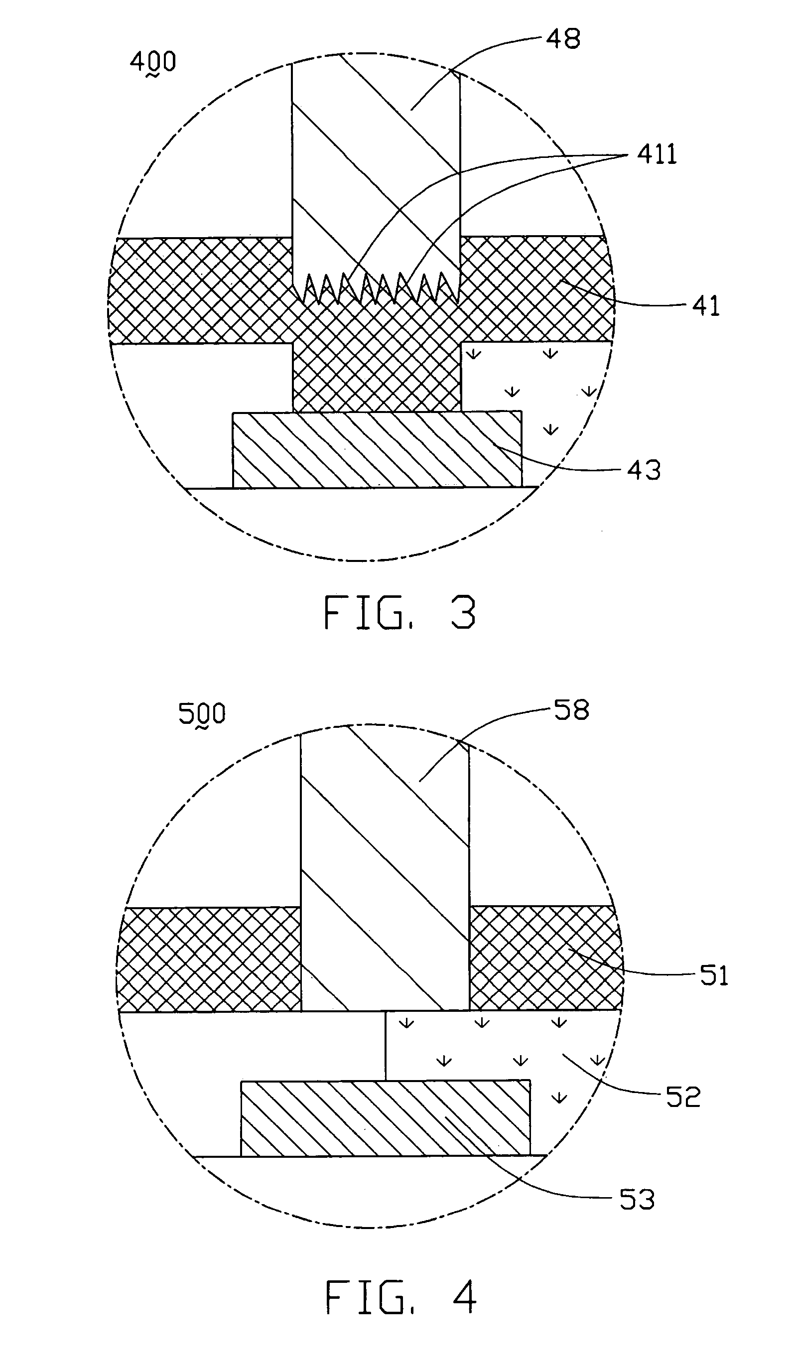
The present invention provides an IPS-LCD with a steady configuration, consistent cell gap, and good display. This is achieved by forming photo spacers between the first and second substrates, which are engaged with an over coat layer tightly and located corresponding to the black matrix. This results in a steady configuration and ensures that all photo spacers have the same height, leading to a consistent cell gap and good display characteristics.

Problems solved by technology

However, the TN mode LCD has a narrow viewing angle.

Method used


Image

  • Color filter and in plane switching type liquid crystal display using the same
  • Color filter and in plane switching type liquid crystal display using the same
  • Color filter and in plane switching type liquid crystal display using the same

Examples


Embodiment Construction

[0023]FIG. 1 is a schematic, side cross-sectional view of part of an IPS-LCD 300 according to the first embodiment of the present invention. The LCD 300 includes a transparent first substrate 34, a transparent second substrate 37 opposite to the first substrate 34, a liquid crystal layer 35 including liquid crystal molecules (not labeled) sandwiched between the substrates 34 and 37, and a plurality of photo spacers 38 formed between the substrates 34 and 37 for supporting the LCD 300 and maintaining the space between the substrates 34 and 37. The substrates 34 and 37 are called a color filter substrate and a TFT (thin film transistor) substrate respectively, and are parallel to each other.

[0024]A plurality of pixel electrodes 362 and a plurality of common electrodes 361 are formed on a surface of the second substrate 37 that faces the first substrate 34. The electrodes 362 and 361 are used for generating an electric field to drive the liquid crystal molecules.

[0025]FIG. 1 also shows...


PUM

PropertyMeasurementUnit
driving electric fieldaaaaaaaaaa
electric fieldaaaaaaaaaa
threshold viewing angleaaaaaaaaaa

Abstract

A color filter includes a substrate, a black matrix located on the substrate, a color layer formed on the substrate, and an over coat layer formed on the substrate to cover the black matrix and the color layer. A plurality of photo spacers are located corresponding to the black matrix, and engage with the over coat layer tightly. Therefore, an IPS LCD using the above-mentioned color filter has a steady configuration, and a cell gap of the LCD is consistent.

Description

BACKROUND OF THE INVENTION[0001]1. Field of the Invention[0002]The present invention relates to a liquid crystal display, and more particularly to an IPS-LCD (in-plane switching liquid crystal display) having photo spacers.[0003]2. Description of Prior Art[0004]In a conventional liquid crystal display, a pair of facing transparent electrodes are respectively formed on two substrates, and are used for driving a liquid crystal layer therebetween. In such a device, a displaying means known as a TN (twisted nematic) display is adopted. That is, the liquid crystal display operates by being supplied with an electric field having a direction orthogonal to inner surfaces of the substrates.[0005]However, the TN mode LCD has a narrow viewing angle. When the user views the display from beyond a threshold viewing angle, he / she cannot see the normal display. That is, the quality of the display greatly depends on the direction of viewing. In order to obtain a wide viewing angle, the IPS type LCD ...

Claims


Application Information

Patent Timeline
Patent Type & Authority Patents(United States)
IPC IPC(8): G02F1/1339G02F1/1335G02F1/1337G02F1/1343
CPCG02F1/13394
Inventor YEH, SHENG-SHIOUWU, MEI LINGPANG, JIA-PANG
Owner INNOLUX CORP
Learn More