

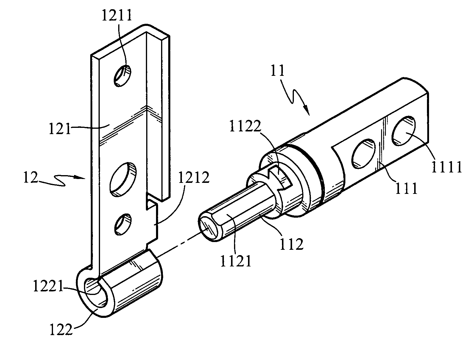
Axle positioning structure
a positioning structure and axle technology, applied in the direction of instruments, wing accessories, details of portable computers, etc., can solve the problems of not taking into account the optimal design of the positioning structure, and the fabrication difficulties, so as to achieve stable positioning, automatic return, and easy and precise fabrication
- Summary
- Abstract
- Description
- Claims
- Application Information
AI Technical Summary
Benefits of technology
Problems solved by technology
Method used
Image

Examples
Embodiment Construction
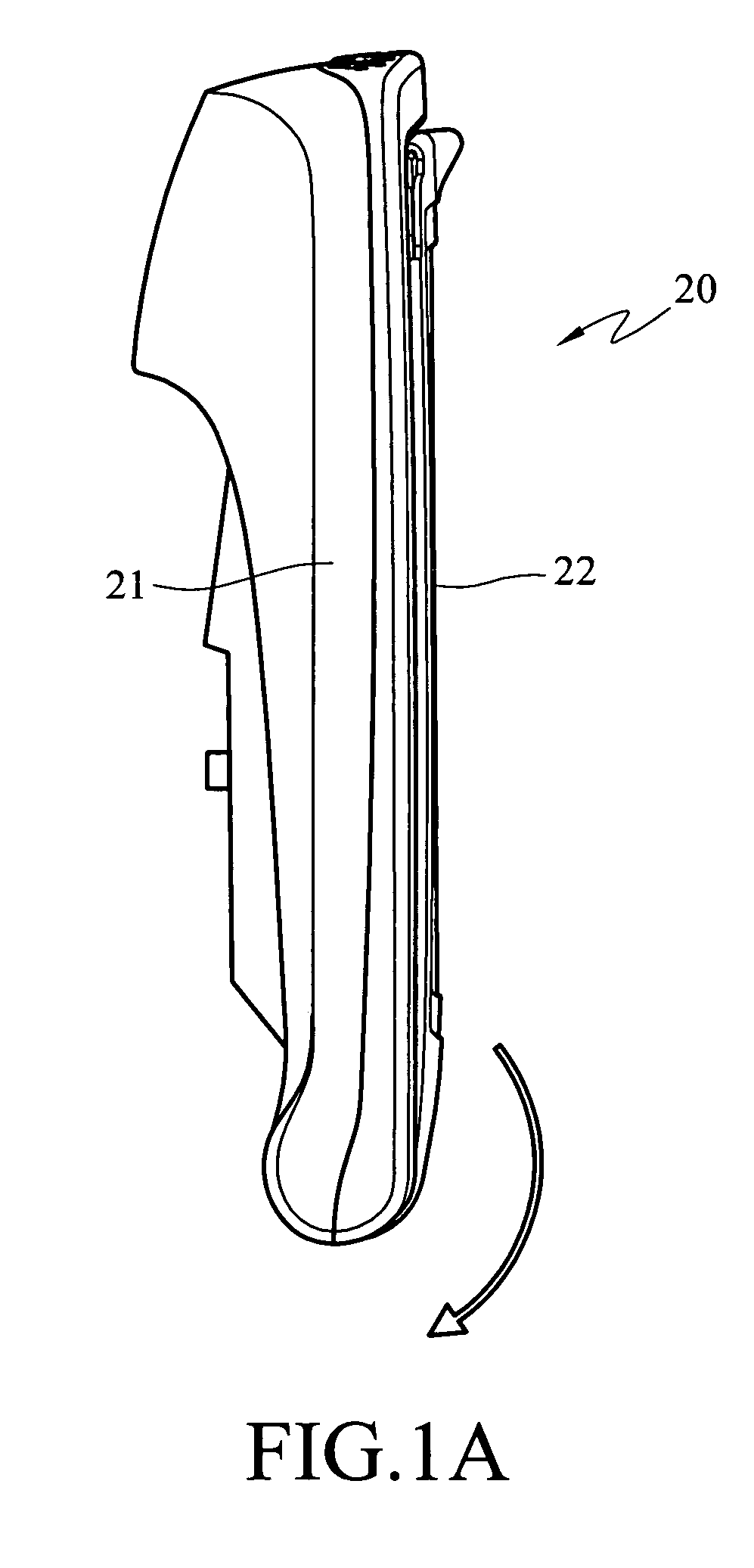
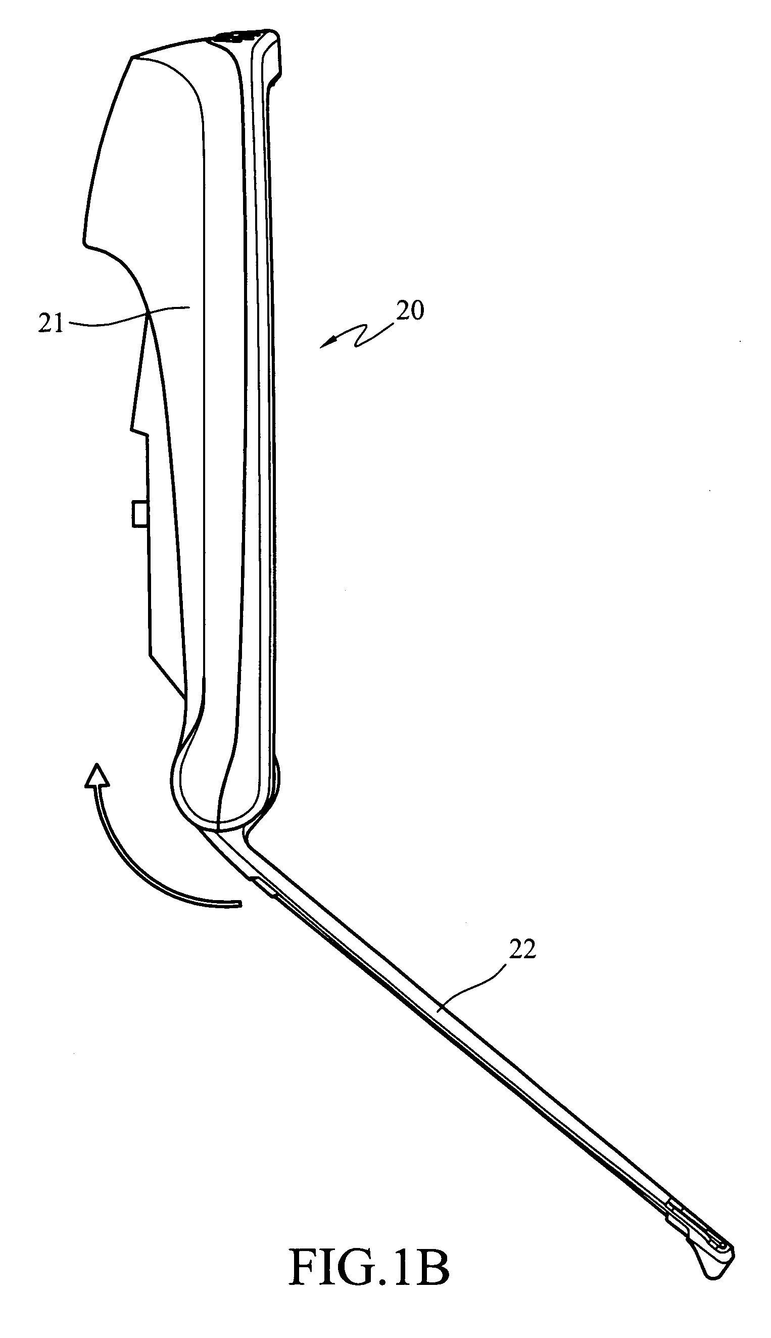
[0015]The axle positioning structure according to the present invention is used to couple a first object and a second object, and enable the first object and the second object to be swiveled relative to each other for folding or forming an angle. The first object and the second object form an electronic device, which may be a flat display device (especially a liquid crystal display Television (LCD TV), notebook computer, personal digital assistant (PDA), mobile phone, or the like. The first object may be a host and the second object may be a display screen. The display screen may be swiveled relative to the host and folded over the host, or be lifted up to form an angle with the host for viewing. Application of the axle positioning structure is not limited to electronic devices. Any device that requires relative folding and opening can adopt the technique disclosed in the present invention. The following description is based on an embodiment of display equipment with a rotary cover ...
PUM
 Abstract
Description
Claims
Application Information