Gas turbine engine frame with an integral fluid reservoir and air/fluid heat exchanger

a technology of gas turbine engine and fluid reservoir, which is applied in the direction of engines, stators, mechanical equipment, etc., can solve the problems of reducing the payload carrying capacity and fuel efficiency of aircraft, consuming a large amount of space, and consuming externally mounted oil tanks and air/oil heat exchangers. , to achieve the effect of reducing engine weight, reducing the risk of rupture, and simplifying maintenan

Active Publication Date: 2008-05-27
RTX CORP
View PDF2 Cites 116 Cited by
  • Summary
  • Abstract
  • Description
  • Claims
  • Application Information

AI Technical Summary

Benefits of technology

[0011]Integrating a fluid reservoir and an air / fluid heat exchanger with a structural frame greatly reduces the risk of rupture due to a fan blade or other rotating component failure. The relocation of components from the external portion of the gas turbine engine also simplifies maintenance and reduces engine weight. Other features and advantages will be apparent from the following more detailed descriptions, taken in conjunction with the accompanying drawings, which illustrate by way of example several embodiments of a structural frame.

Problems solved by technology

Also, externally mounted oil tanks and air / oil heat exchangers consume a vast amount of space, complicating maintenance of other components.
The oil tank, air / oil heat exchanger and associated mounting brackets increase an engine's weight, which reduces the payload carrying capacity and fuel efficiency of an aircraft.

Method used


Image

  • Gas turbine engine frame with an integral fluid reservoir and air/fluid heat exchanger
  • Gas turbine engine frame with an integral fluid reservoir and air/fluid heat exchanger
  • Gas turbine engine frame with an integral fluid reservoir and air/fluid heat exchanger

Examples


Embodiment Construction

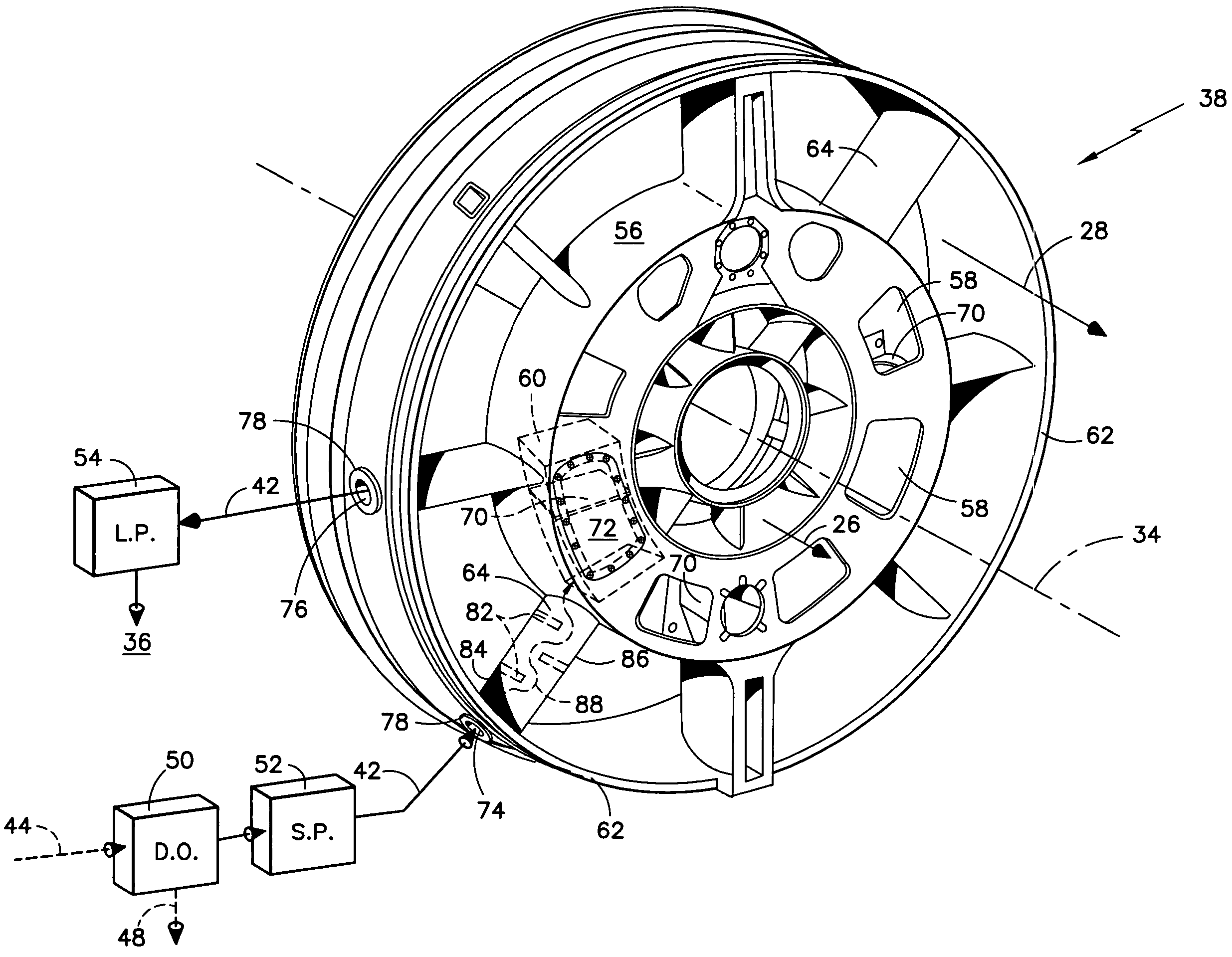
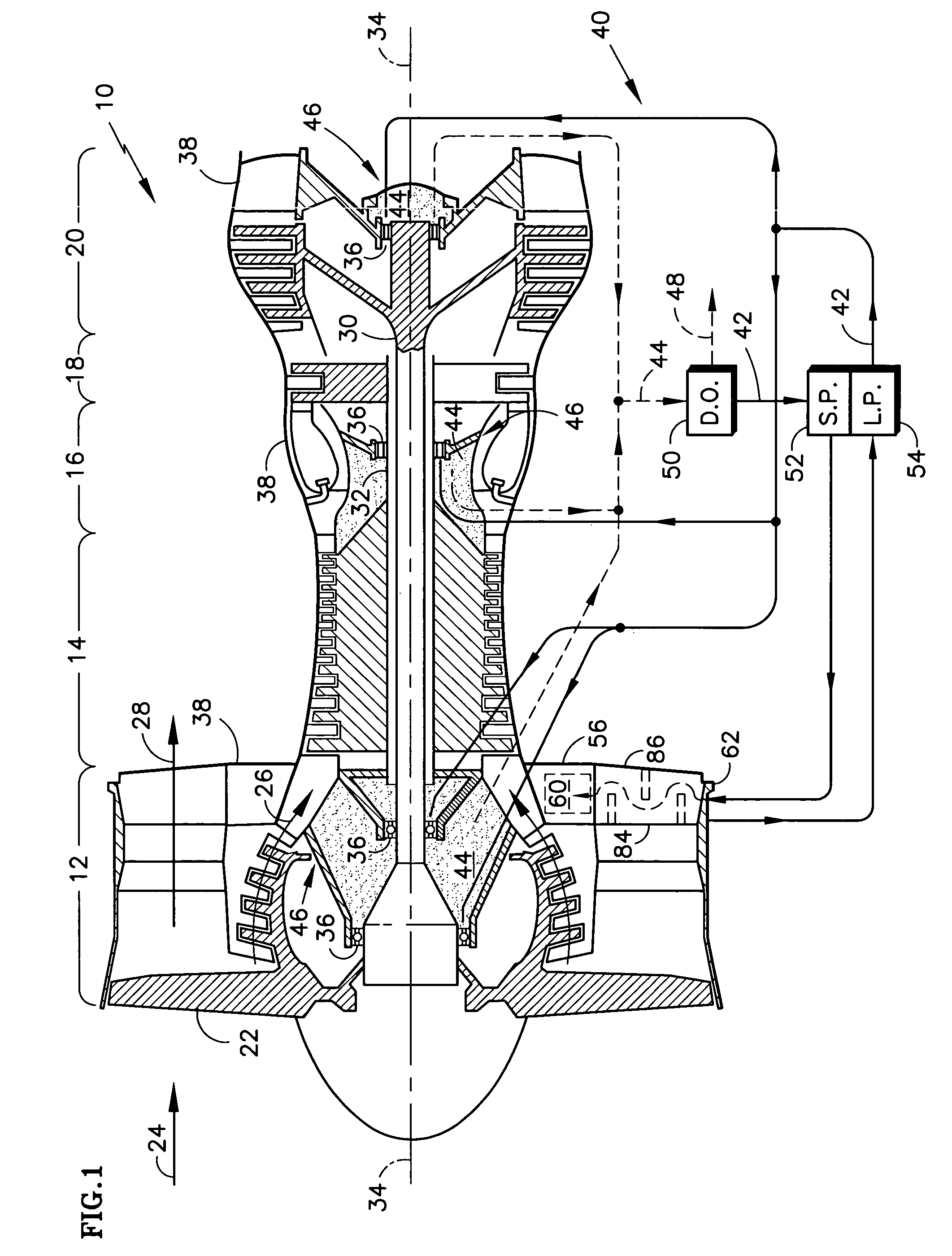
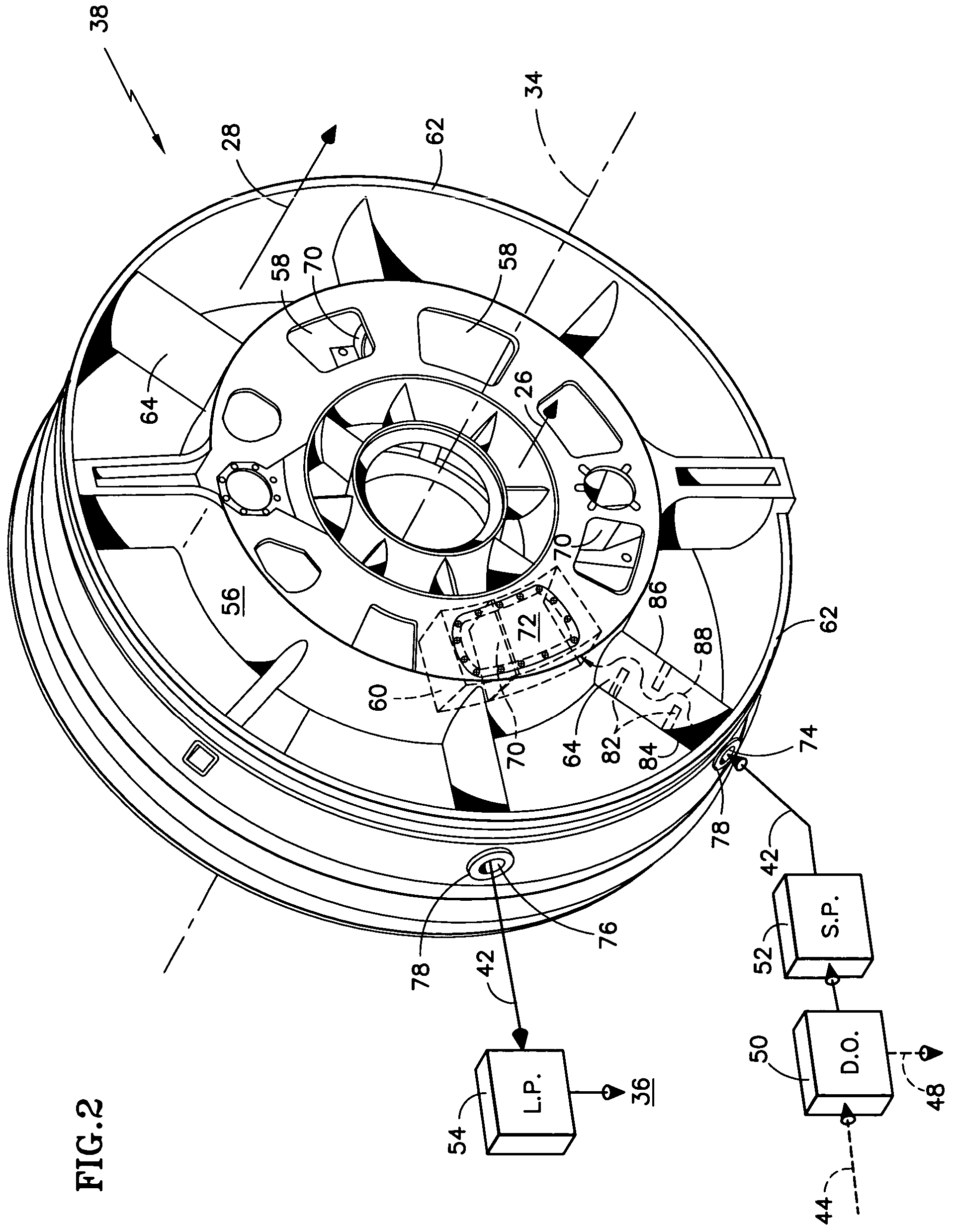
[0021]The major sections of a gas turbine engine 10 of FIG. 1 are a low pressure compressor 12, a high pressure compressor 14, a combustor 16, a high pressure turbine 18 and a low pressure turbine 20. The forward most stage of the low pressure compressor 12, normally referred to as a fan stage 22, directs incoming air 24 into two portions: core air 26 and bypass air 28. The core air 26 is directed inside the aforementioned sections and the bypass air 28 is directed outside of the aforementioned sections. The low pressure compressor 12 is coupled to the low pressure turbine 20 by a low rotor shaft 30 and the high pressure compressor 14 is coupled to the high pressure turbine 18 by a high rotor shaft 32. The shafts 30, 32 are concentric and rotate about a central longitudinal axis 34 of the gas turbine engine 10.

[0022]The shafts 30, 32 are supported by bearings 36 from one or more structural frames 38 that are stationary. In the example shown, three structural frames 38 support the sh...


PUM


Abstract

Disclosed is a structural frame for a gas turbine engine comprising an integral fluid reservoir and air / fluid heat exchanger. A central hub includes a reservoir for storing a fluid and an outer rim circumscribes the hub. A heat exchanger is fluidly coupled to the reservoir and is in simultaneous communication with the fluid and an air stream.

Description

BACKGROUND OF THE INVENTION[0001](1) Field of the Invention[0002]The invention relates to gas turbine engine components, and more particularly to a structural frame comprising an integral fluid reservoir and air / fluid heat exchanger.[0003](2) Description of the Related Art[0004]In axial-flow gas turbine engines, incoming air is pressurized in a forward compressor section and directed axially rearward through a diffuser to a combustion chamber. In the combustion chamber, fuel is injected into the pressurized air and the resulting fuel / air mixture is burned. Hot combustion gases expand into a rearward turbine section, where energy is extracted, before exiting the gas turbine engine as an exhaust jet.[0005]The turbine section is comprised of alternating axial stages of rotating blades and stationary vanes. The turbine blades transfer the extracted energy to one or more rotor assemblies, which are coupled to the aft ends of one or more central shafts. The shafts extend axially forward a...

Claims


Application Information

Patent Timeline
Patent Type & Authority Patents(United States)
IPC IPC(8): F02C7/06F02C7/12
CPCF01D9/065F01D25/162F01D25/18F02C7/14Y02T50/671Y02T50/675Y02T50/60
Inventor WALKER, HERBERT L.AKERLEY, STEVAN W.
Owner RTX CORP
Why Eureka
Try Eureka