Seatbelt retractor having an inertial sensor weight with a guide surface

a technology of inertial sensor and guide surface, which is applied in the direction of belt retractors, vehicle safety belts, vehicle components, etc., can solve the problems of significant noise, and achieve the effect of increasing the initial sensor reaction sensitivity and reducing the overall sensor sensitivity

Inactive Publication Date: 2008-05-27
KEY SAFETY SYST
View PDF11 Cites 20 Cited by
  • Summary
  • Abstract
  • Description
  • Claims
  • Application Information

AI Technical Summary

Benefits of technology

[0007]The guide surface can be shaped or formed with a unique profile to lessen noise and provide more positive locking and unlocking of the actuator.
[0008]The guide surface has an inner profile region wherein the actuator rests in the unlocked position at the near zero acceleration position that is inclined less than15°, preferably less than 10° or even 5°, most preferably substantially flat. The inner profile region can extend across the entire guide surface of the inertial mass sensor to the full locked position of the actuator. In such a case the tilting of the sensor positively accelerates the actuator as it is pushed by the substantially flat or low angled inner profile on the guide surface. This creates a soft start contact between the sensor and the actuator thereby reducing rattle noise.
[0009]In a second embodiment of the invention the guide surface has an outer profile region which actually is curved to provide a deceleration of the actuator as it is being moved into the locked position. In this embodiment the inner profile of the actuator can be any shape that provides an initial positive acceleration of the actuator as the inertial sensor moves towards the locking position. At an inflection point or surface, between the inner profile creating a positive acceleration of the actuator and the outer profile, the acceleration transitions from positive to negative enabling the actuator to slow its impact velocity with the locking pawl or locking mechanism of the seatbelt retractor. This creates a “soft” locking impact further reducing locking noise.
[0010]The third embodiment of the present invention combines the inner profile and the outer profile with a middle transitional profile interposed between the two profiles. The actuator rests on the initial profile at near zero or low vehicle accelerations and moves quickly onto a ramped or inclined transitional profile having an increasing inclination to create a more positive acceleration of the actuator. This combination of profiles insures the actuator sees very little or no movement at low or near zero accelerations and decelerations of the vehicle relative to the inertial sensor. When the acceleration or deceleration of the vehicle is severe enough to tilt the sensor the rapid movement in the transitional profile enables the actuator to be more rapidly moved towards the locking position. Once nearing that position the actuator slides past an inflection point onto the outer profile and begins to decelerate slowing the velocity of the actuator thereby reducing the impact of the locking pawl and the associated locking mechanisms thereby softening the impact and reducing the noises generated upon moving into a locking position.
[0014]Hence, movement of the actuator is controlled by the shape of the guide surface of the inertial mass. Indeed, the actuator may have more than one acceleration rate as it moves across the guide surface. By controlling the rate of acceleration of the actuator, noise is also controlled without reducing the overall sensor sensitivity significantly, in some cases actually increasing the initial sensor reaction sensitivity.

Problems solved by technology

The inventor has discovered that a significant amount of noise arises from movement of the actuator and components linked to it.

Method used


Image

  • Seatbelt retractor having an inertial sensor weight with a guide surface
  • Seatbelt retractor having an inertial sensor weight with a guide surface
  • Seatbelt retractor having an inertial sensor weight with a guide surface

Examples


Embodiment Construction

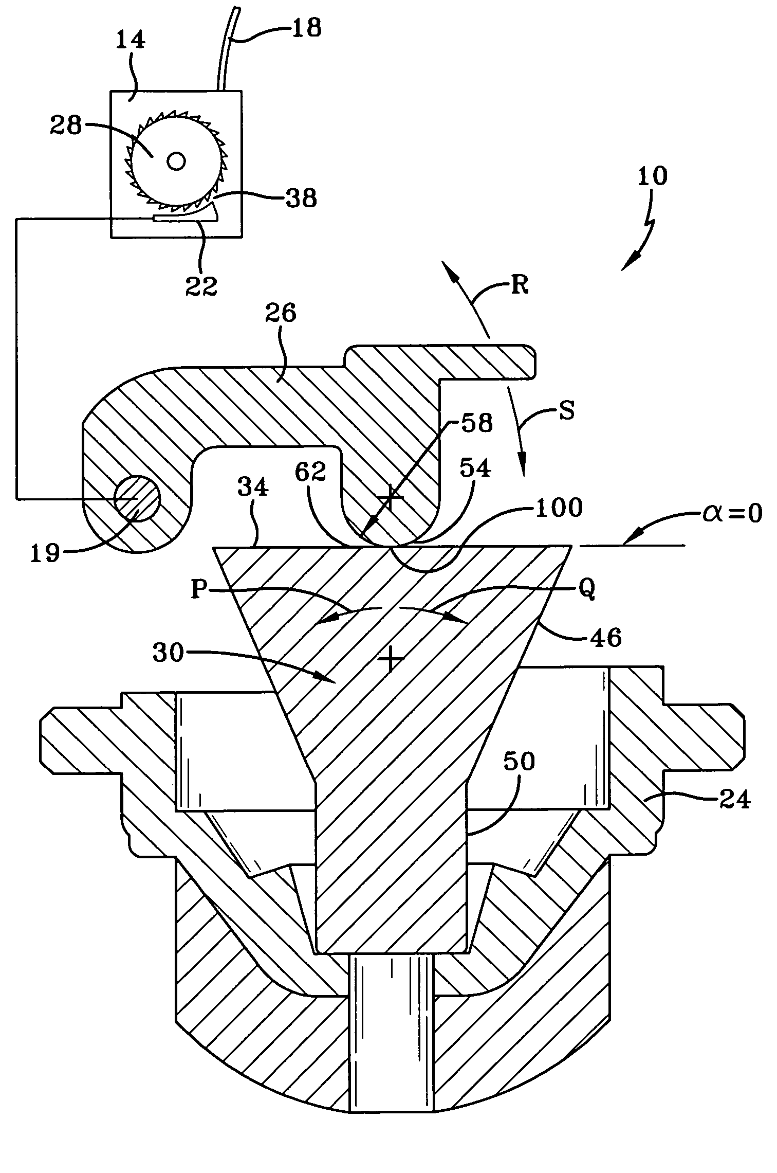
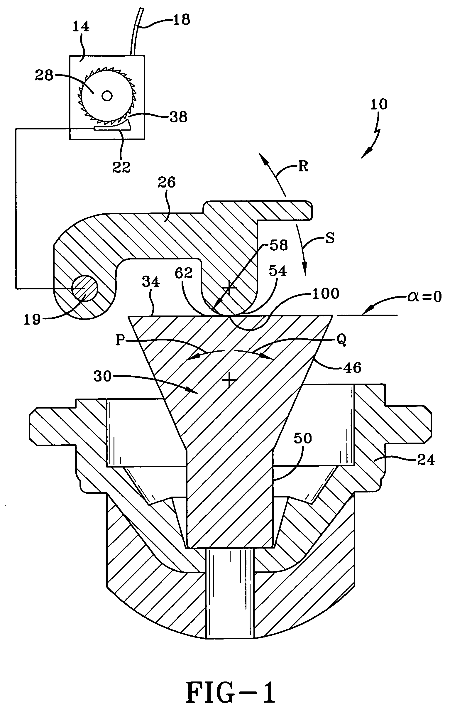
[0027]FIG. 1 is a side view of an inventive seatbelt retractor assembly 10. The seatbelt retractor assembly 10 has a seatbelt retractor 14, which houses a seatbelt 18 as shown. Like conventional seatbelt retractors, the seatbelt retractor assembly 10 has a locking pawl 22, which is selectively engageable with a locking wheel 28. The locking wheel 28 has teeth to engage the locking pawl 22. When the locking pawl 22 is engaged with the locking wheel 22, the seatbelt retractor 14 prevents the seatbelt 18 from extending further from seatbelt retractor 14.

[0028]As shown, the seatbelt retractor 14 has an inertial sensor, here an inertial sensor mass 30, which is responsive to vehicle acceleration. The inertial sensor mass 30 rests on a sensor housing 24, here shown schematically, and tips in the direction of either arrow P or arrow Q in response to vehicle acceleration. The inertial sensor mass 30 is linked to the locking pawl 22 by an actuator 26, an arm, which causes the locking pawl 22...


PUM


Abstract

A seatbelt retractor assembly (10) has a seatbelt retractor (14) and an actuator (26) for locking and unlocking the seatbelt retractor (1). An inertial sensor mass (30, 32, 33) detects changes in vehicle speed. The mass (30, 32, 33) has a guide surface (34, 35, 36) for interacting with the actuator (26). The guide surface (34, 35, 36) moves between an unlocking position in which the actuator (26) unlocks the seatbelt retractor (14) and a locking position in which the actuator (26) locks the seatbelt retractor (14). The guide surface (30) has an inner profile portion (62) and at least an outer profile portion (64). The actuator (26) is in contact with the inner profile portion (62) in the unlocking position while moving into contact with the outer profile portion (64) as the actuator (26) moves towards the locking position. The inner profile portion (62) causes a different acceleration of the actuator (26) than the outer profile portion (64).

Description

FIELD OF THE INVENTION[0001]This invention relates to a seatbelt retractor assembly.BACKGROUND OF THE INVENTION[0002]A seatbelt for a passenger vehicle typically has a seatbelt retractor that serves to retract the belt into its housing. The belt is wound upon a spool in the housing. When the belt is drawn or protracted from its housing, the spool winds a retraction spring, which later retracts the unused portion of the belt onto the spool or withdraws the belt into its housing when not in use.[0003]In the event of a crash, the seatbelt retractor has a lock that prevents the seatbelt from extending further from its housing. The lock may be actuated by an inertial sensor, which responds to changes in vehicle speed during the crash. When a large deceleration is detected, the inertial sensor triggers the lock of the seatbelt retractor to lock the spool and thereby secures the safety belt in place during the crash.[0004]The inertial sensor has an inertial sensor mass that moves in respon...

Claims


Application Information

Patent Timeline
Patent Type & Authority Patents(United States)
IPC IPC(8): B65H75/48
CPCB60R22/40
Inventor MORGAN, CHRISTOPHER D.
Owner KEY SAFETY SYST
Why Eureka
Try Eureka