
Variable gain differential amplifier, and variable degeneration impedance control device and method for use in the same

a variable gain, differential amplifier technology, applied in differential amplifiers, amplifiers with semiconductor devices/discharge tubes, amplifier control details, etc., can solve the problems of inability to ensure linearity of amplifiers

Inactive Publication Date: 2008-05-27
SAMSUNG ELECTRONICS CO LTD
View PDF2 Cites 7 Cited by
  • Summary
  • Abstract
  • Description
  • Claims
  • Application Information

AI Technical Summary

Benefits of technology

[0014]The present invention addresses the above-mentioned drawbacks and other problems associated with the conventional amplifier arrangements. An aspect of the present invention is to provide a variable gain differential amplifier which can adjust the amplification gain and ensure the linearity.
[0015]Another aspect of the present invention is to provide a variable degeneration impedance control device for use in a variable gain differential amplifier, which can adjust the amplification gain and ensure the linearity.
[0016]Still another aspect of the present invention is to provide a variable degeneration impedance control method for use in a variable gain differential amplifier, which can adjust the amplification gain and ensure the linearity.

Problems solved by technology

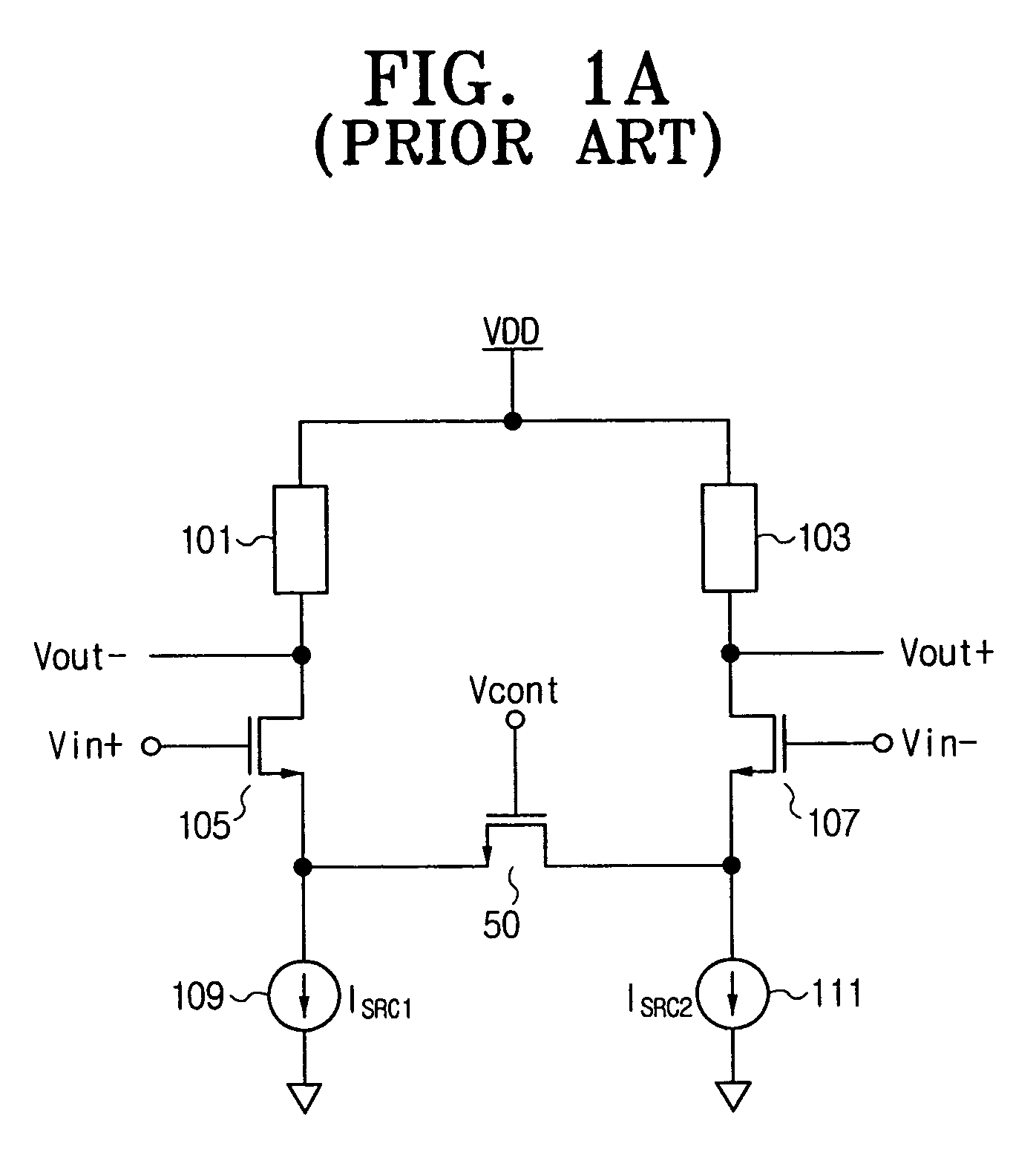
However, the triode region L, in which the linearity is ensured, is too narrow since it is limited to the vicinity of the origin.
Accordingly, if a large signal is applied between the drain and the source, the linearity of the amplifier cannot be ensured.
Consequently, the conventional amplifier shown in FIG. 1A can adjust the gain level, but cannot ensure the linearity sufficiently.
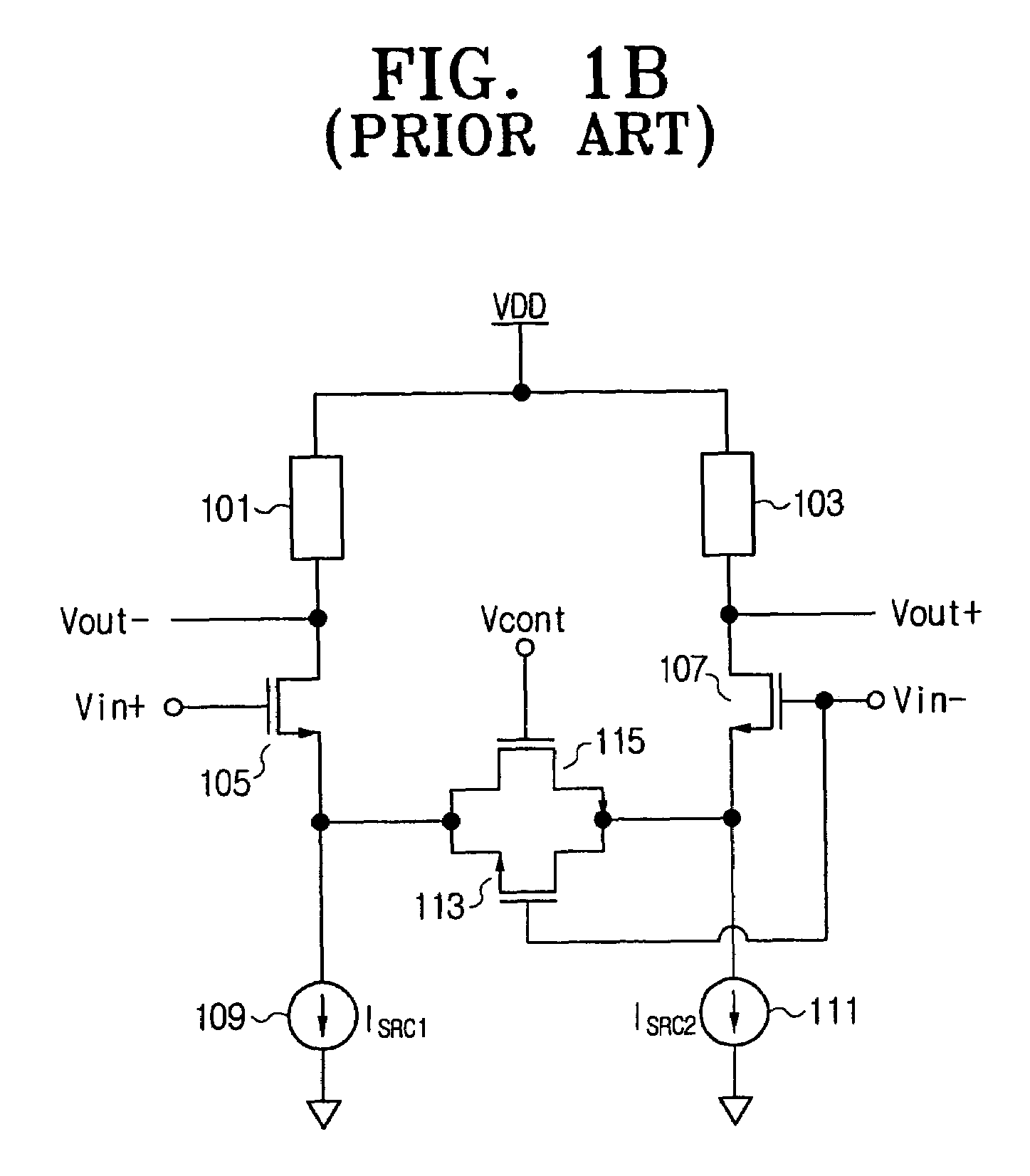
Accordingly, the conventional amplifier shown in FIG. 1B can ensure the linearity, but cannot adjust the gain level since the DC levels of the gain input differential signals are fixed.

Method used


Image

  • Variable gain differential amplifier, and variable degeneration impedance control device and method for use in the same
  • Variable gain differential amplifier, and variable degeneration impedance control device and method for use in the same
  • Variable gain differential amplifier, and variable degeneration impedance control device and method for use in the same

Examples


Embodiment Construction

[0035]Certain exemplary embodiments of the present invention will be described in greater detail with reference to the accompanying drawings.

[0036]In the following description, same drawing reference numerals are used for the same elements even in different drawings. The matters defined herein are described at a high-level of abstraction to provide a comprehensive yet clear understanding of the invention. It is also to be noted that it will be apparent to those ordinarily skilled in the art that the present invention is not limited to the description of the exemplary embodiments provided herein.

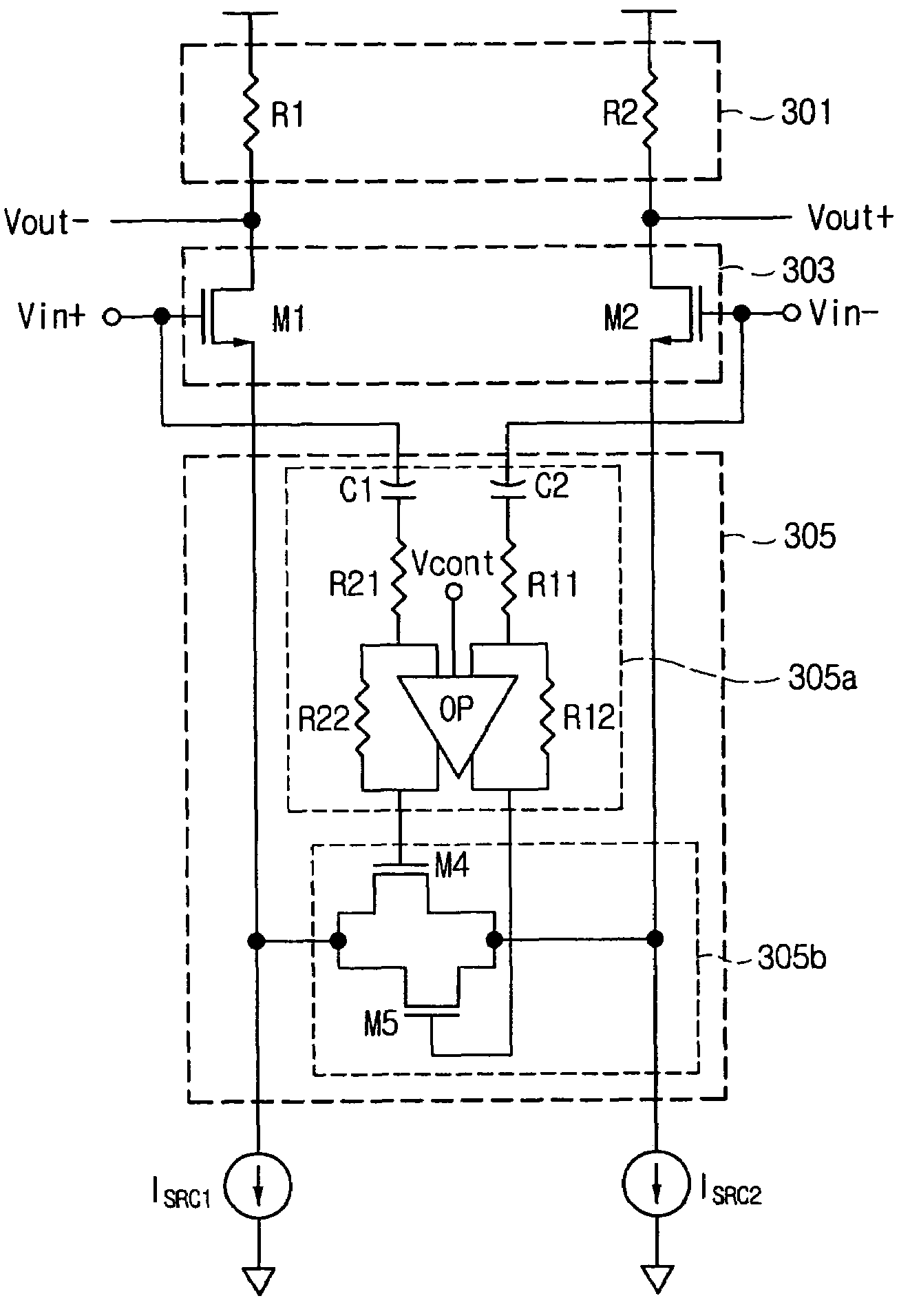
[0037]FIG. 3 is a schematic circuit diagram of a variable gain differential amplifier according an exemplary embodiment of the present invention.

[0038]Referring to FIG. 3, the variable gain differential amplifier includes a load 301, a differential amplifying part 303, and a variable degeneration impedance part 305.

[0039]The variable amplifying part 303 has input terminals for receiving diffe...


PUM


Abstract

Disclosed are a variable gain differential amplifier, and variable degeneration impedance control device and method for use in the variable gain differential amplifier, which can adjust an amplification gain and ensure linearity. A DC level of a differential signal to be amplified by the amplifier is adjusted according to a control signal to adjust a gain of the amplifier, and the impedance of a variable degeneration impedance part is adjusted according to the differential signal of which the DC level is adjusted. That is, the gain of the differential amplifier is adjusted and the linearity is ensured by varying the impedance of the variable degeneration impedance part using the differential input signal of which the DC level is adjusted.

Description

CROSS-REFERENCE TO RELATED APPLICATIONS[0001]This application claims priority under 35 U.S.C. § 119 from Korean Patent Application No. 2005-13788, filed on Feb. 18, 2005, the entire content of which is incorporated herein by reference.BACKGROUND OF THE INVENTION[0002]1. Field of the Invention[0003]The invention relates to a variable gain differential amplifier, and variable degeneration impedance control device and method for use in the same, and more particularly, to a variable gain differential amplifier that has both linearity and gain adjustment.[0004]2. Description of the Related Art[0005]A variable gain amplifier (VGA) is an amplifier that can adjust a gain by receiving and amplifying a difference between signals (hereinafter referred to as “differential signal”).[0006]Commercialized devices that use variable gain amplifiers may be personal digital assistants (PDAs), mobile communication devices, cellular phones, wireless two-way data communication devices, etc.[0007]FIG. 1A i...

Claims


Application Information

Patent Timeline
Patent Type & Authority Patents(United States)
IPC IPC(8): H03F3/45
CPCH03G1/0029H03F3/45H03G3/30H03F1/32
Inventor SUH, CHUN-DEOKKIM, HOON-TAELEE, JUNG-EUN
Owner SAMSUNG ELECTRONICS CO LTD
Learn More