Flat thin screen TV/monitor automotive roof mount

a thin screen, tv/monitor technology, applied in the direction of roofs, television systems, transportation and packaging, etc., can solve the problems of screen not being able to swing forward, unsafe or inconvenient to use, and hazard to passengers, so as to achieve convenient displacement

Inactive Publication Date: 2008-05-27
VOXX INT CORP
View PDF319 Cites 60 Cited by
  • Summary
  • Abstract
  • Description
  • Claims
  • Application Information

AI Technical Summary

Benefits of technology

[0012]The display self aligns as it reaches either of the first and second positions. Force acting on the edge of the display as it approaches the roof or the housing causes the display to rotate about the second axis until the display is substantially parallel to the roof. The rotational capability of the display, 180° in one direction and between 60° and 90° in another, allows the display to be easily displaced when contacted by a passenger or other object. Thus, the display does not pose a significant hazard to a passenger who inadvertently bumps into it, either casually or during a vehicle collision.
[0013]When the display is in the storage position, the display screen desirably faces, and is safely enclosed by, the housing. The display screen is protected from damage in this position, and passengers are protected from broken pieces of the display screen as might result from a vehicle collision.

Problems solved by technology

However, current overhead consoles for video display screens include features that make them either unsafe or inconvenient to use, or both.
The principal drawback of the '030 device is the hazard that it poses to passengers.
Due to the design of the pivots and the obstruction posed by the console body, the screen cannot swing forward any farther than this position.
Thus, it poses a significant obstacle for passengers moving within the vehicle.
A passenger who is thrown forward during a collision could be seriously injured by striking the screen.
Another drawback of the '030 design is the limited range of viewing positions available for the display screen.
This drawback is especially acute if the display screen is an LED, which can only be seen from a narrow range of angles in front of the screen.

Method used


Image

  • Flat thin screen TV/monitor automotive roof mount
  • Flat thin screen TV/monitor automotive roof mount
  • Flat thin screen TV/monitor automotive roof mount

Examples


Embodiment Construction

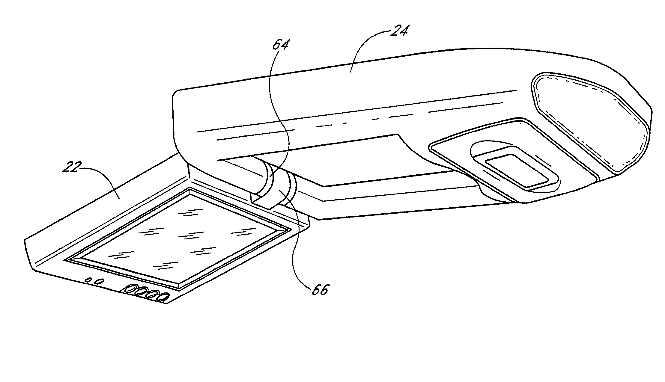
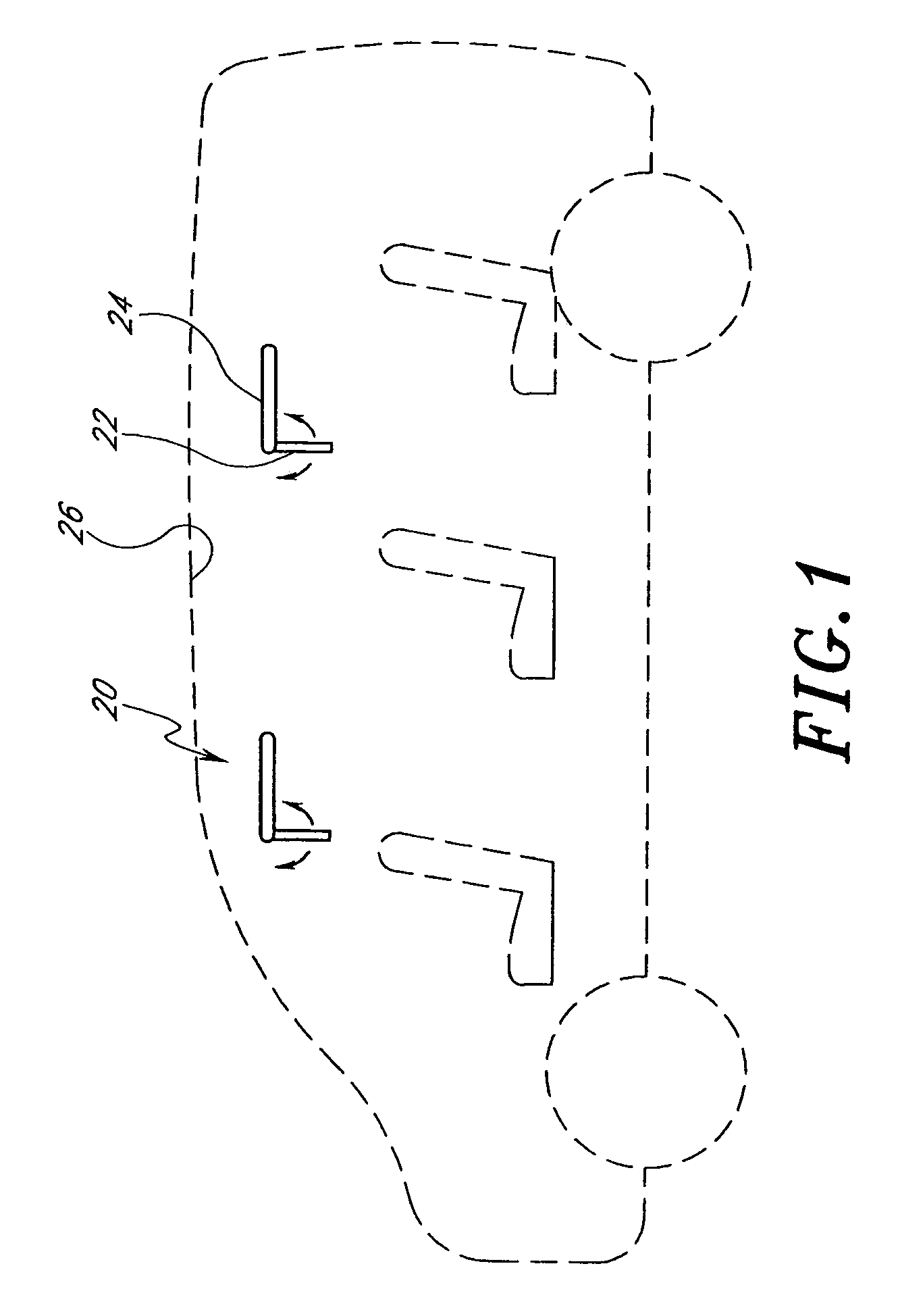
[0025]The invention provides a vehicle roof mount 20 for a video display 22, as illustrated in FIG. 1. It will be understood by one of skill in the art that the invention may be used to mount, among others, television monitors or navigation units that receive airborne signals, as well as closed circuit monitors that receive signals from a source within the vehicle. For the sake of simplicity, the term “display” or “video display” will be used throughout to refer to the visual display component of the invention. No intention to limit the scope of the invention to any particular type of visual display is implied.

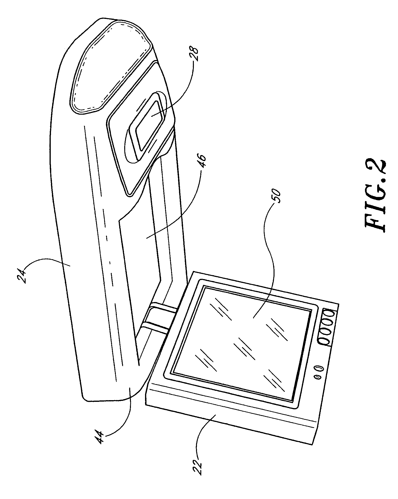
[0026]The vehicle roof mount 20 of the present invention comprises a housing 24 adapted to be secured to the interior of a vehicle roof 26, and a video display 22 hingedly attached to the housing 24. FIG. 2 illustrates the display 22 in a viewing position. The housing 24 features an integrated dome light 28 to facilitate manipulation of the various controls of the invention, w...


PUM


Abstract

A vehicle roof mounted video display is disclosed. The display is rotatable 180° about a first axis, between a stored position within a housing and a second position in which the display lies flat against the vehicle roof. The display is also rotatable at least 60°, and preferably 90°, about a second axis that intersects and is substantially perpendicular to the first axis. Each axis includes self-tensioning hinges to hold the display in any position. The display self aligns as it reaches either of the first and second positions so that the display is substantially parallel to the roof. When the display is in the storage position, the display screen faces, and is safely enclosed by, the housing. The invention also includes a number of built-in features to provide passengers with a wide range of entertainment options.

Description

RELATED APPLICATION[0001]This application is a continuation of application Ser. No. 10 / 120,552, filed on Apr. 9, 2002, now abandoned which is a continuation of application Ser. No. 09 / 717,928, filed on Nov. 21, 2000, now U.S. Pat. No. 6,409,242 which claims priority to provisional application Ser. No. 60 / 248,981, filed on Nov. 14, 2000. The entirety of each of these applications is hereby incorporated by reference herein.BACKGROUND OF THE INVENTION[0002]1. Field of the Invention[0003]The invention relates to devices for mounting video displays on the inside surface of an automobile roof. More specifically, the device provides a vehicle mounted video display that incorporates a wide range of entertainment options, is convenient to use and poses little risk of harm to passengers.[0004]2. Description of the Related Art & Summary of the Invention[0005]Overhead consoles for vans and other large vehicles are well known. One type of overhead console contains a video display screen and othe...

Claims


Application Information

Patent Timeline
Patent Type & Authority Patents(United States)
IPC IPC(8): H04N5/64B60R11/00B60R11/02
CPCB60R11/0235B60K2350/922B60R2011/0028B60R2011/0082B60R2011/0087B60R2011/0294B60K2370/771
Inventor CHANG, CHUNG L.
Owner VOXX INT CORP
Why Eureka
Try Eureka