Detector configuration for interferometric distance measurement

a technology of interferometer and detector configuration, which is applied in the direction of interferometers, measurement devices, instruments, etc., can solve the problems of affecting the accuracy, complexity, and/or reliability of the detector used for phase difference measurement, and the resolution and/or accuracy of the polarization interferometer are often limited,

Active Publication Date: 2008-05-27
MITUTOYO CORP
View PDF10 Cites 5 Cited by
  • Summary
  • Abstract
  • Description
  • Claims
  • Application Information

AI Technical Summary

Benefits of technology

[0012]According to one feature of this invention, it is not necessary to control both the transmissive and reflective differential phase shifts at each beam splitting surface in a detector, in order to eliminate their potential error contributions. Rather, components, surface orientations, and beam polarization directions are arranged such that as the reference beam and object beam components traverse various surfaces and / or coatings, induced phase shifts due to the surface and / or coatings interactions are made to be as similar as possible between the s-components of both the reference beam and object beam, and various output signals are formed by mixing these s-components exclusively. Similarly, surface and / or coatings interactions are made to be as similar as possible between the p-components of both the reference beam and object beam, and various output signals are formed by mixing these p-components exclusively. Thus, the majority of phase shifts induced at the various surfaces and / or coating in a detector according to this invention are arranged to be “common mode” phase shifts in the interference signals that are output from the detector. Such common mode phase shifts do not contribute a net error in the phase difference represented in the interference signals, resulting in a more accurate measurement of the phase difference between the reference beam and object beam components. The resulting improvements in accuracy are important when attempting to increase the measurement resolution and accuracy of an interferometer to smaller fractions of a wavelength of light. In addition, the reduction and / or elimination of differential phase shifts within a detector is achieved in a particularly robust, simple and cost-effective manner in various embodiments according to this invention.
[0014]According to a separate feature of the invention, if a phase shifting element is located to receive light transmitted by a beam splitting surface, then it is sufficient if ΔTP-S is adjusted to be insignificant before the transmitted light reaches the phase shifting element. Similarly, if a phase shifting element is located to receive light reflected by a beam splitting surface, then it is sufficient if ΔRP-S is adjusted to be insignificant. This overcomes the previously indicated difficulty of simultaneously controlling both ΔTP-S and ΔRP-S, and makes it practical to provide the desired adjustment of ΔTP-S or ΔRP-S, as well as providing a desired intensity splitting ratio, in a beam spitting coating. In some embodiments, the beam splitter surface coating may also include component layers that provide the phase-shifting element.
[0015]In general, in conventional beam splitter coatings, ΔRP-S may be significantly larger than ΔTP-S. Therefore, while adjusting ΔRP-S may be a practical alternative, it may be more reliable and less expensive to adjust ΔTP-S to an insignificant level using a beam splitting coating. Accordingly, a detector may be configured such that all phase shifting elements receive beams transmitted at beam splitting surfaces where ΔTP-S is adjusted to insignificance. Errors that may otherwise arise due to uncontrolled ΔRP-S may then be negated by other previously described features of the invention.

Problems solved by technology

The resolution and / or accuracy of a polarization interferometer is often limited by the ability of the phase difference detector, also referred to simply as a detector herein, to generate one or more measurement signals which are truly related only to the phase difference between the object and reference beams output from the interferometer.
Conventional configurations of the quadrature-type detectors outlined above typically introduce unwanted “differential phase shifts” between the reference and object beam components that interfere to form the various output signals.
In any case, such errors may adversely affect the accuracy, complexity, and / or reliability of a detector used for phase difference measurements.
As previously indicated, conventional detector arrangements typically include errors that arise because, in practice, conventional detectors may introduce unwanted differential phase shifts between the reference and object beam components that interfere to form the various output signals.
They may also contribute to errors that alter the ideal phase relationships between the various outputs of the detector.
It is generally difficult and / or prohibitively expensive to fabricate beamsplitter coatings that simultaneously control both of transmissive and reflective differential phase shifts as well as the desired ratio between the transmitted and reflected beam intensities.
However, despite the foregoing feature of the invention, in the absence of additional care, errors may still arise in association with phase-shifting elements used in a detector.
In such a case, the resulting interference signals used for determining a phase difference will not be the ideal signals desired.

Method used


Image

  • Detector configuration for interferometric distance measurement
  • Detector configuration for interferometric distance measurement
  • Detector configuration for interferometric distance measurement

Examples


Embodiment Construction

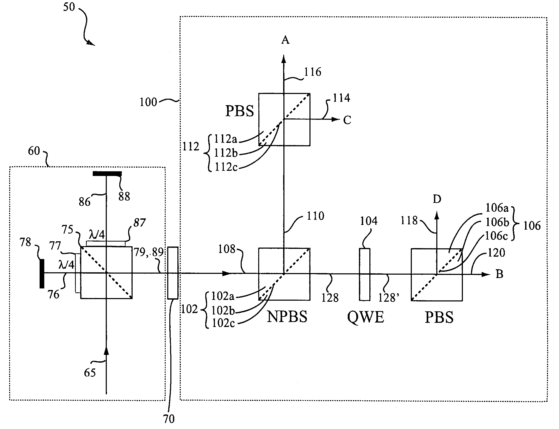
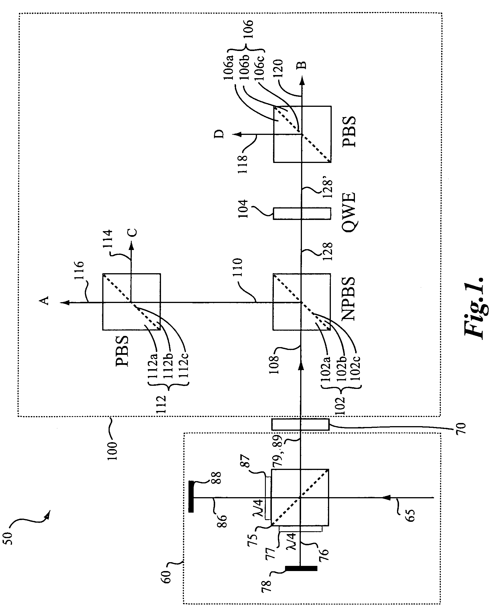
[0026]FIG. 1 shows a schematic diagram of an exemplary interferometric distance measuring apparatus 50, including an interferometer portion 60 and a detector 100. In the interferometer portion 60, a laser source (not shown) may be used to generate coherent radiation 65. The radiation 65 may pass through appropriate components (not shown) to adjust the polarization of the radiation 65 as desired, and it is then incident on a polarizing beam splitter 75, which may transmit the portion of the radiation 65 that is “p” polarized to form reference beam 86, and reflect the portion of the radiation that is “s” polarized to form object beam 76. The reference beam 86 is transmitted through a quarter wave plate 87 to a fixed reference mirror 88 and reflected back through the quarter wave plate 87 to reach the polarizing beam splitter 75. Its polarization is now rotated 90° relative to its initial transmission through the polarizing beamsplitter 75. Thus, it is reflected by the polarizing beam ...


PUM


Abstract

A phase difference detector generates a plurality of signals from an input beam including orthogonal, linearly polarized object and reference beam components. The detector may be configured such that as the reference and object beam components traverse the detector, phase shifts due to surface interactions are made as similar as possible between the s-components of the reference object beams, and between the p-components of the reference and object beams. Various outputs may be formed by interfering p-components exclusively, or s-components exclusively, negating errors that may otherwise arise due to differential phase shifts between p- and s-components. Phase-shifting elements in the detector may receive beams from beam splitting surfaces where the transmissive differential phase shift between p- and s-components is adjusted to insignificance.

Description

BACKGROUND OF THE INVENTION[0001]1. Field of Invention[0002]This invention is directed to detectors for interferometric distance measuring and surface profiling devices.[0003]2. Description of Related Art[0004]Laser interferometers are widely used to measure distances or displacements. One type, polarization interferometers, may form an output beam having two orthogonal, linearly polarized components—a reference beam component and an object beam component. The desired distance or displacement measuring information is carried by the phase difference between the orthogonal, linearly polarized reference and object components of the combined output beam.[0005]Numerous schemes have been devised for measuring this phase difference. In one common scheme, a quadrature-type phase difference detector is used. Quadrature-type phase difference detectors typically divide the combined output beam from the interferometer into multiple beams, typically four beams, and intentionally introduce a diff...

Claims


Application Information

Patent Timeline
Patent Type & Authority Patents(United States)
IPC IPC(8): G01B9/02
CPCG01B9/02G01B2290/70G01B9/02081G01B2290/45
Inventor FELDMAN, MARK
Owner MITUTOYO CORP
Why Eureka
Try Eureka