System and method of wireless instant messaging

a wireless instant messaging and wireless technology, applied in the field of instant messaging, can solve the problems of increasing network traffic and reducing the battery life of stations

Active Publication Date: 2008-05-27
MALIKIE INNOVATIONS LTD
View PDF7 Cites 19 Cited by
  • Summary
  • Abstract
  • Description
  • Claims
  • Application Information

AI Technical Summary

Benefits of technology

[0009]A system and method of instant messaging is provided. A plurality of messaging clients capable of transmitting instant messages to one another are each configured to share presence information with one another via a network. A determination is made, with respect to each of the messaging clients, as to whether the messaging client is in a state in which it is receptive to receiving presence information from the other messaging clients, and if so, then the presence information is provided to the messaging client. The presence information may be provided directly between the messaging clients, or it may be provided through one or more centralized proxy servers that store and propagate the presence information. A special state is provided, referred to herein as the unknown state, which when entered by a particular messaging client will cause the system to cease further transmissions of presence information to that client. Upon changing to a communicative state, the system resumes providing presence information to the messaging client.

Problems solved by technology

This continuous transmission of presence information, regardless of the state of the stations, can result in increased network traffic and a reduction in station battery life, particularly when the station is a wireless mobile communication device.
Furthermore, traditional IM techniques may assume that the users are not always activated and always connected to the network—which may not always be the case with certain wireless network users that maintain constant connectivity.

Method used


Image

  • System and method of wireless instant messaging
  • System and method of wireless instant messaging
  • System and method of wireless instant messaging

Examples


first embodiment

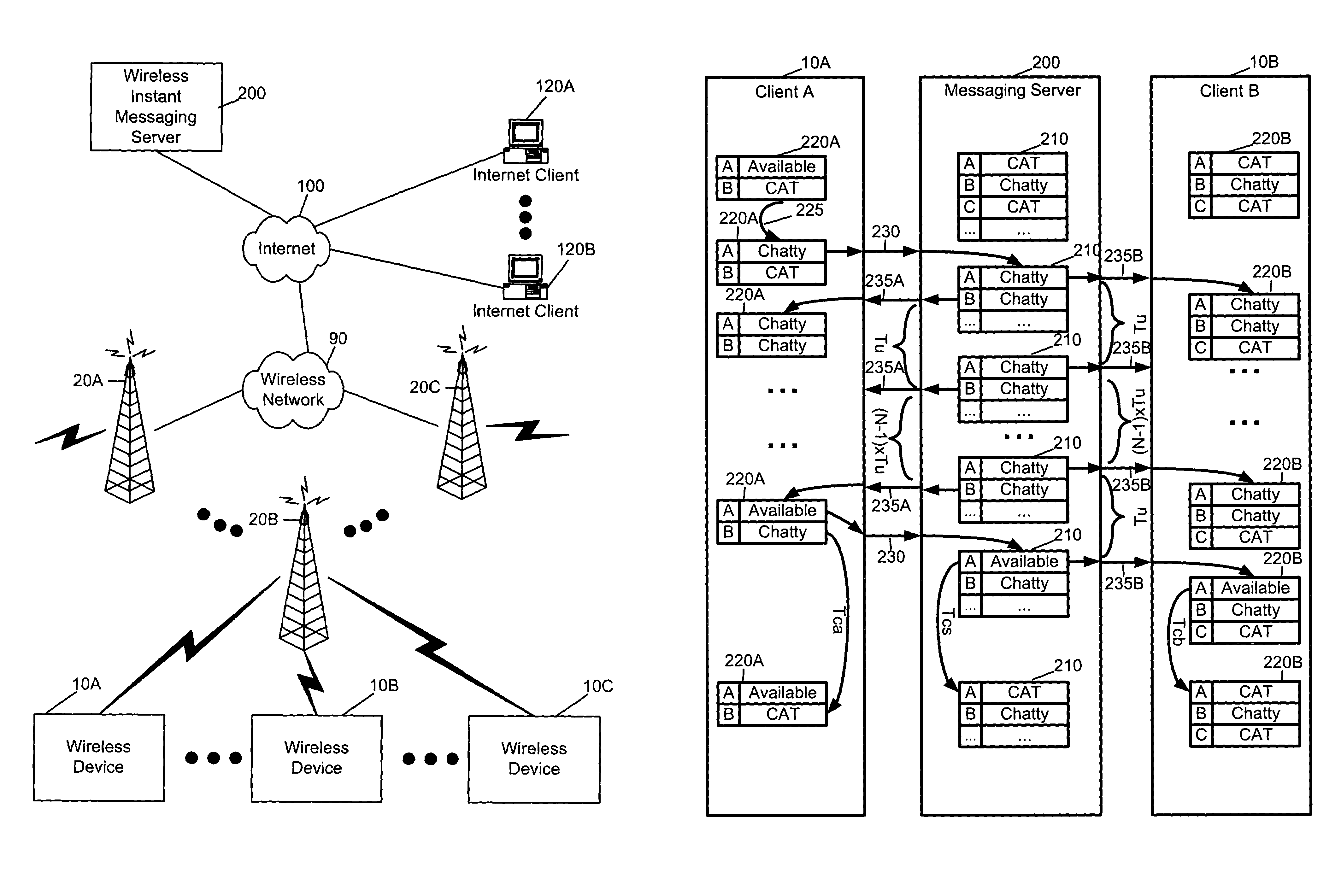
[0033]FIG. 3 is an interaction diagram illustrating steps of a method of wireless instant messaging in accordance with the present invention. Messaging server 200 communicates with client applications on wireless devices A and B (10A and 10B), as well as with other client applications, such as C. In FIG. 3, an arrow between messaging server 200 and clients 10A, B illustrate communications. The relative time between these communications is illustrated by time flowing generally downward so that if a first arrow is higher than a second arrow in FIG. 3, this is meant to illustrate that the first communication occurred before the second communication.

[0034]Messaging server 200 keeps track of presence information. As illustrated, initially messaging server 200 has a server presence table 210 having one row per wireless client A, B, C, etc., wherein each row stores the presence state for each wireless client. As shown, client 10B is initially in the “chatty” state according to table 210, w...

second embodiment

[0041]FIG. 4 is an interaction diagram illustrating steps of a method of wireless instant messaging in accordance with the present invention. FIG. 4 shows communications between messaging server 200 and client 10A illustrating in greater detail steps surrounding updates queued by wireless network 90 when client 10A falls out of coverage. Client 10A and messaging server 200 originally have presence information tables 220A and 210, respectively. As was the case in FIG. 3, a trigger 225 at client 10A causes client 10A to enter the “chatty” state. Client 10A then changes its state from “Available” to “chatty” in response to the trigger 225—for instance when the user of client 10A activates the instant messaging application. Client 10A then communicates 230A its new state information to the messaging server 200, which tracks and updates the change in table 210.

[0042]At messaging server 200, both clients 10A and 10B are now in the “chatty” state. Messaging server 200 sends client state up...

third embodiment

[0047]FIG. 5 is an interaction diagram illustrating steps of a method of wireless instant messaging in accordance with the present invention.

[0048]A wireless device 10A sends a single message 300A addressed to a group GID1 via wireless messaging server 200. Group GID1 is a unique identifier which is resolved by messaging server by consulting a database 310 that relates group ids such as GID1320 to user ids 330, such as UID1, . . . ,UIDN. As shown, messaging server 200 then sends messages 340B-C to each wireless device having user ids 330, as well as sending messages 350A-B to internet clients 120A-B. This mechanism ensures that wireless device 10A only needs to transmit one wireless message 300A in order to reach multiple wireless users 10B-C and internet users 120A-B.


PUM


Abstract

A system and method of instant messaging is provided. A plurality of messaging clients capable of transmitting instant messages to one another are each configured to share presence information with one another via a network. A determination is made, with respect to each of the messaging clients, as to whether the messaging client is in a state in which it is receptive to receiving presence information from the other messaging clients, and if so, then the presence information is provided to the messaging client. The presence information may be provided directly between the messaging clients, or it may be provided through one or more centralized proxy servers that store and propagate the presence information. A special state is provided, referred to herein as the unknown state, which when entered by a particular messaging client will cause the system to cease further transmissions of presence information to that client and / or transmissions about that client. Upon changing to a communicative state, the system resumes providing presence information to / about the messaging client.

Description

CROSS-REFERENCE TO RELATED APPLICATIONS[0001]This application claims priority to U.S. Provisional Application Ser. No. 60 / 412,818, filed on Sep. 24, 2002, the entire disclosure of which, including the drawing figures, is hereby incorporated by reference into this application.BACKGROUND[0002]1. Field of the Invention[0003]This invention relates generally to the field of instant messaging. More particularly, the invention provides a system and method of instant messaging to and from wireless devices.[0004]2. Description of the Related Art[0005]Known Instant Messaging (IM) techniques typically send short messages and maintain presence information. One technique for maintaining presence information is the “buddy list.” In a “buddy list,” users keep a list of correspondents that they regularly communicate with. Correspondents in a “buddy list” typically poll each other for presence information, such as correspondent active, disconnected, etc. The users can glance through the “buddy list”...

Claims


Application Information

Patent Timeline
IPC IPC(8): H04M3/42H04L12/58H04L29/08H04W4/06H04W4/12H04W8/18
CPCH04L12/581H04L51/04H04W4/12H04L67/24H04L67/14H04L12/5895H04W4/06H04W8/18H04L51/58H04L67/54Y02D30/70
Inventor BELLS, MATTHEWHAIGH, DAVID M.
Owner MALIKIE INNOVATIONS LTD
Why Eureka
Try Eureka