Milling tooth and milling tooth holder for a comminution machine

Inactive Publication Date: 2008-06-03
FAE GROUP
View PDF13 Cites 32 Cited by
  • Summary
  • Abstract
  • Description
  • Claims
  • Application Information

AI Technical Summary

Benefits of technology

[0009]Greater strength and durability of the milling tooth are achieved by

Problems solved by technology

However, the desired action is limited, particularly in the case

Method used


Image

  • Milling tooth and milling tooth holder for a comminution machine
  • Milling tooth and milling tooth holder for a comminution machine
  • Milling tooth and milling tooth holder for a comminution machine

Examples


Example

DETAILED DESCRIPTION OF THE DRAWING

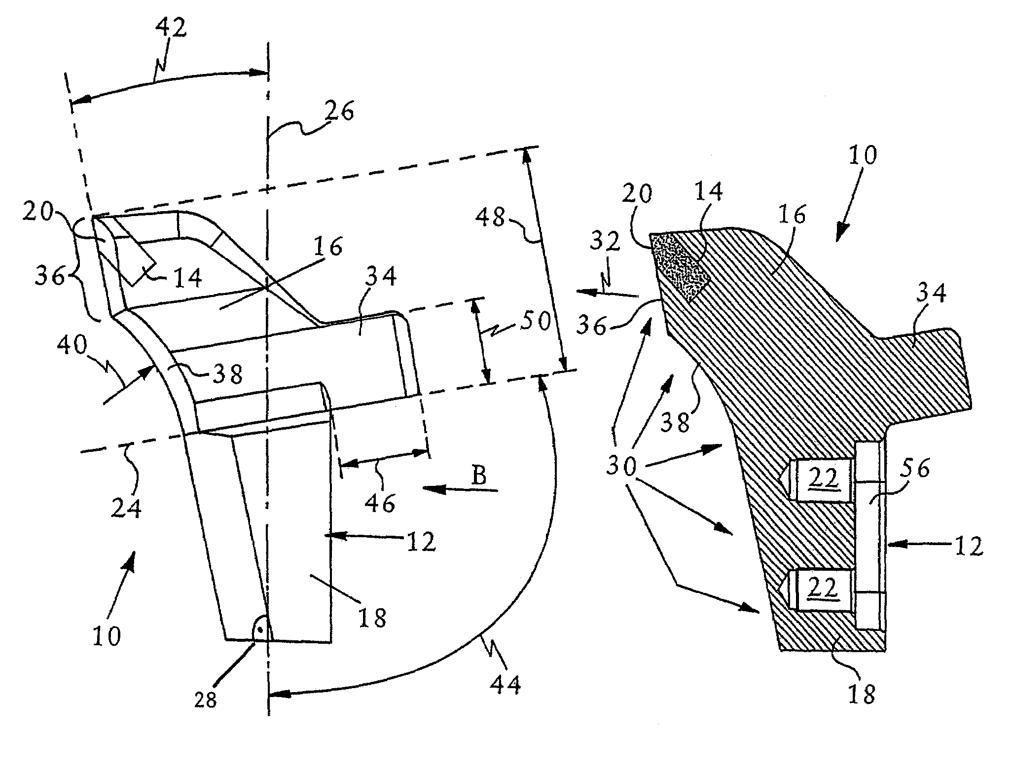
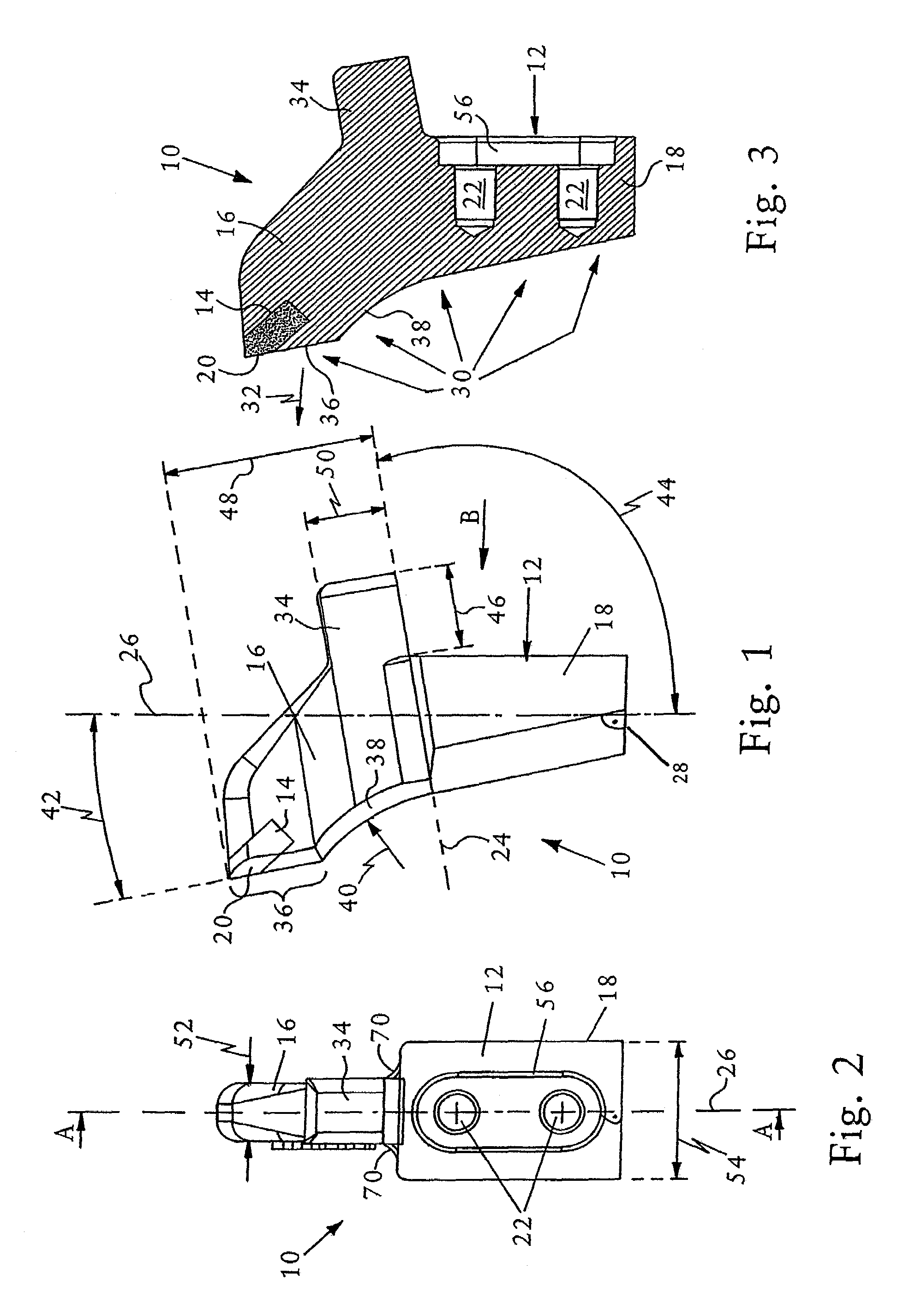
[0020]The preferred embodiment, shown in FIGS. 1 to 3, of a milling tooth 10 for a comminution machine, not shown in its entirety, comprises a milling tooth body with a flange side 12 for detachable connection to a milling tooth holder of the comminution machine, a recess 14, a milling tooth tip 16 on the side of the recess 14 and a milling tooth base 18 on the end of the milling tooth body facing away from the milling tooth tip 16. Arranged in the recess 14 is a cutting device 20 in the form of two hard metal parts. These hard metal parts are, for example, soldered into the recess 14. Accessible from the flange side 12, in the milling tooth body, are two threaded holes 22, by means of which a braced fastening to the milling tooth holder is carried out. For this purpose, in each case a screw reaches through the milling tooth holder into the threaded hole 22, as will be described later in detail in relation to FIG. 7.

[0021]The milling tooth tip 16 i...


PUM


Abstract

A milling tooth body for a comminution machine has a working side, oriented in a working direction; a flange side detachably connected to a milling tooth holder of the comminution machine; a tooth tip on the side of a recess; and a base at an end of the tooth body facing away from the tooth tip. A cutter device is in the recess. The flange side on the tooth body is opposite the working side. An entire side of the tooth body, which is oriented in the working direction, is the working side. The tooth tip projects away from the flange side in the direction of a longitudinal axis of the tooth body, perpendicular to the working direction. A first section of the tooth body projects away from the flange side in a direction parallel to and opposite the working direction.

Description

RELATED APPLICATIONS[0001]The present application is based on, and claims priority from, Germany Application Number DE 201 16 344.6, filed Oct. 5, 2001 and International Application Number PCT / EP02 / 11227, filed Oct. 7, 2002, the disclosures of which are hereby incorporated by reference herein in their entirety.FIELD OF THE INVENTION[0002]The present invention relates to a milling tooth for a comminution machine, a milling tooth holder for a comminution machine and a comminution machine having a milling tooth holder.BACKGROUND OF THE INVENTION[0003]Milling teeth in the form of brush cutter flails or the like for earth working machines, such as mowers, choppers or mulchers, are disclosed by U.S. Pat. No. 3,678,671, DE 199 51 086 or EP 0 182 122, for example. These milling teeth are generally mounted in a sprung manner on a rotating drum, so that sudden mechanical effects or shocks on account of stones or the like do not lead to immediate destruction of the milling teeth involved. Howe...

Claims


Application Information

Patent Timeline
IPC IPC(8): B27C1/14A01B33/10A01B33/14B02C18/18
CPCA01B33/103B02C18/18A01B33/142Y10T407/1932Y02A40/28
Inventor PIZZUTO, GIAN-FRANCO
Owner FAE GROUP
Why Eureka
Try Eureka