Method of forming industrial housings

a technology of industrial housing and housing plate, which is applied in the direction of gearing, other domestic objects, mechanical equipment, etc., can solve the problems of slow manufacturing, increase manufacturing cost, and both methods of forming housing plate have known drawbacks, so as to achieve cost savings, material savings, and greater thickness

Active Publication Date: 2012-08-30
SZUBA CONSULTING +1
View PDF11 Cites 8 Cited by
  • Summary
  • Abstract
  • Description
  • Claims
  • Application Information

AI Technical Summary

Benefits of technology

[0009]The method of forming a housing from a steel tube of this invention has several important advantages over the prior art. First the method of this invention results in a substantial savings in cost. In a conventional method of forming a housing by stamping, the scrap rate is typically greater than 30% and depending upon the blank-out system, the material savings may exceed 50%. Further, the method of this invention may be utilized to form a housing having a greater thickness at specific areas and is thus thick only where needed for weight and material ...

Problems solved by technology

However, both of the methods of forming housings have known drawbacks.
Where a housing is formed by casting, the method results in excessive mass and typically an imbalance in the component in which the housing is implemented and has resulted in quality problems.
Further, cast housings are slow to manufacture due to cooling requirements in a casting dye, ...

Method used


Image

  • Method of forming industrial housings
  • Method of forming industrial housings
  • Method of forming industrial housings

Examples


Embodiment Construction

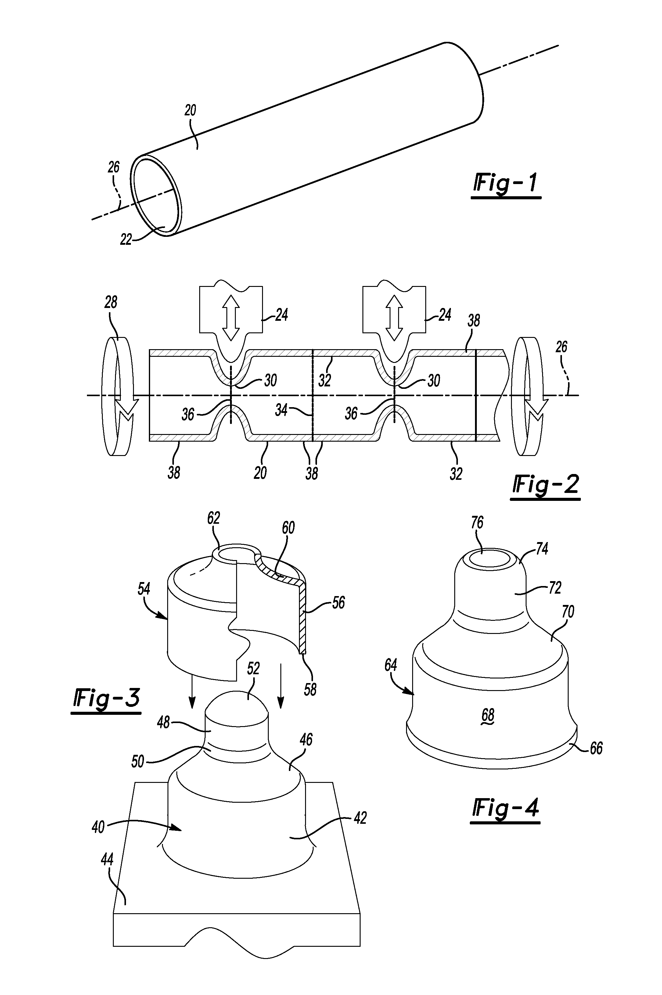
[0022]FIG. 1 illustrates a conventional steel pipe or tube 20 which may be utilized in the method of forming a housing of this invention. The conventional steel tube or pipe 20 has an axial or longitudinal bore 22 and may be formed of any steel, including low and high carbon steels and high strength low alloy (HSLA) steels depending upon the ultimate application of the housing. The diameter and thickness of the tube wall will also depend upon the application and may range for example from 1 mm to 0.5 inches. The tube 20 may include a welded seam (not shown) but the tube may also be seamless depending upon the application. However, a welded seam tube is significantly less expensive than a seamless tube and a welded seam tube is suitable for most applications.

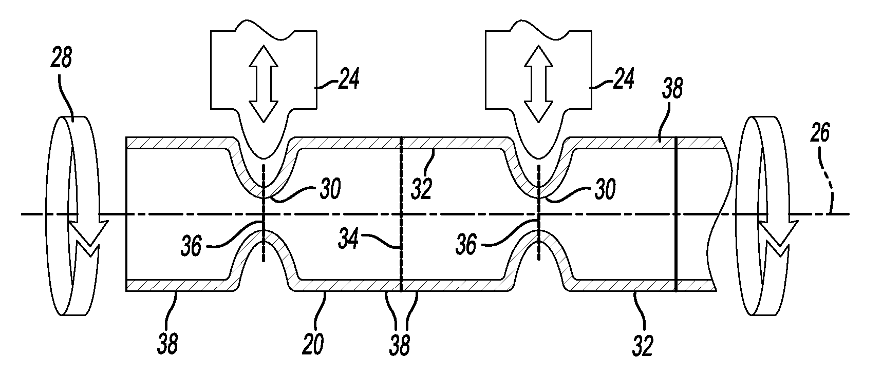
[0023]FIG. 2 illustrates one step in the method of forming a housing of this invention, wherein a plurality of rollers 24 roll form the steel tube 20 radially inwardly. In a preferred embodiment, the rollers 24 extend generally p...


PUM

PropertyMeasurementUnit
Fractionaaaaaaaaaa
Fractionaaaaaaaaaa
Fractionaaaaaaaaaa

Abstract

A method of forming a housing which includes roll forming a steel tube radially inwardly with a plurality of rollers each having a rolling axis parallel to the longitudinal axis of the tube, the rollers compressing the tube and forming reduced diameter portions and enlarged diameter portions. The method then includes cutting the tube perpendicular to the longitudinal axis generally midway through an enlarged diameter portion and a reduced diameter portion, forming a plurality of minor image preforms. Finally, the method includes cold working the preforms into the desired shape of the housing and increasing the strength of the steel at least 15% and forming a housing member having enlarged diameter open end and a reduced diameter open end.

Description

BACKGROUND OF THE INVENTION[0001]This application claims priority to U.S. Provisional Patent Application No's. 61 / 510,601, filed on Jul. 22, 2011 and 61 / 446,552 filed on Feb. 25, 2011.[0002]Various shapes and types of housings have been used in the automotive and other industries for as long as such industries have existed. These housings have been typically formed from castings when structural performance is required or formed from steel plates or sheets using a stamping process. However, both of the methods of forming housings have known drawbacks.[0003]Where a housing is formed by casting, the method results in excessive mass and typically an imbalance in the component in which the housing is implemented and has resulted in quality problems. Further, cast housings are slow to manufacture due to cooling requirements in a casting dye, which is also known to increase the cost of manufacturing.[0004]Where the housing is formed by stamping a metal sheet or plate, expensive, significan...

Claims


Application Information

Patent Timeline
IPC IPC(8): B21D15/06B21D26/033B21C37/15B21D22/00
CPCB21K1/26B21B17/02B21K21/16F16H48/08B21H7/00Y10T29/49826B21D22/16F16H48/00F16H48/40B21D17/04
Inventor SZUBA, JOSEPH
Owner SZUBA CONSULTING
Why Eureka
Try Eureka