Aerodynamic device for vehicle
a technology for aerodynamic devices and vehicles, which is applied in the direction of roofs, vehicle arrangements, transportation and packaging, etc., can solve the problems of difficult to suppress the inflow of air and disturb the flow of air at the side of the front wheel
- Summary
- Abstract
- Description
- Claims
- Application Information
AI Technical Summary
Benefits of technology
Problems solved by technology
Method used
Image
Examples
second exemplary embodiment
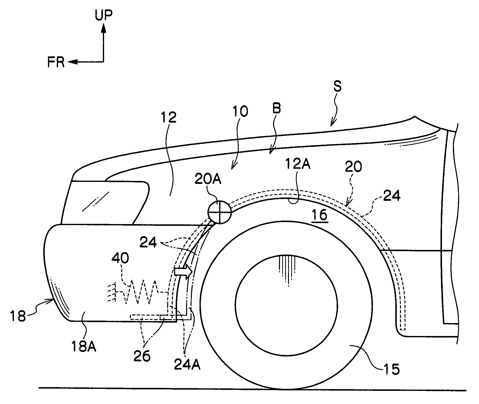
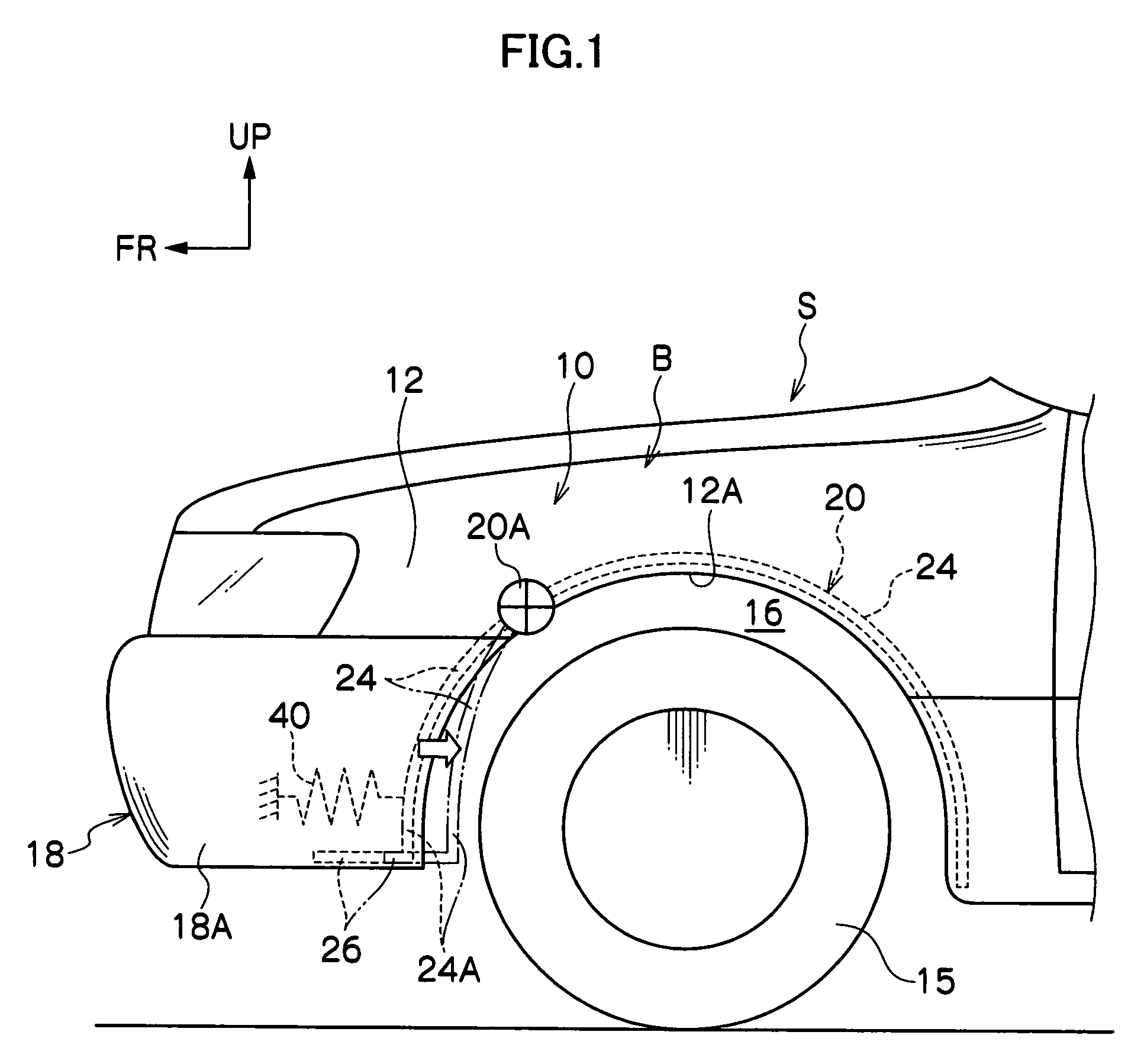
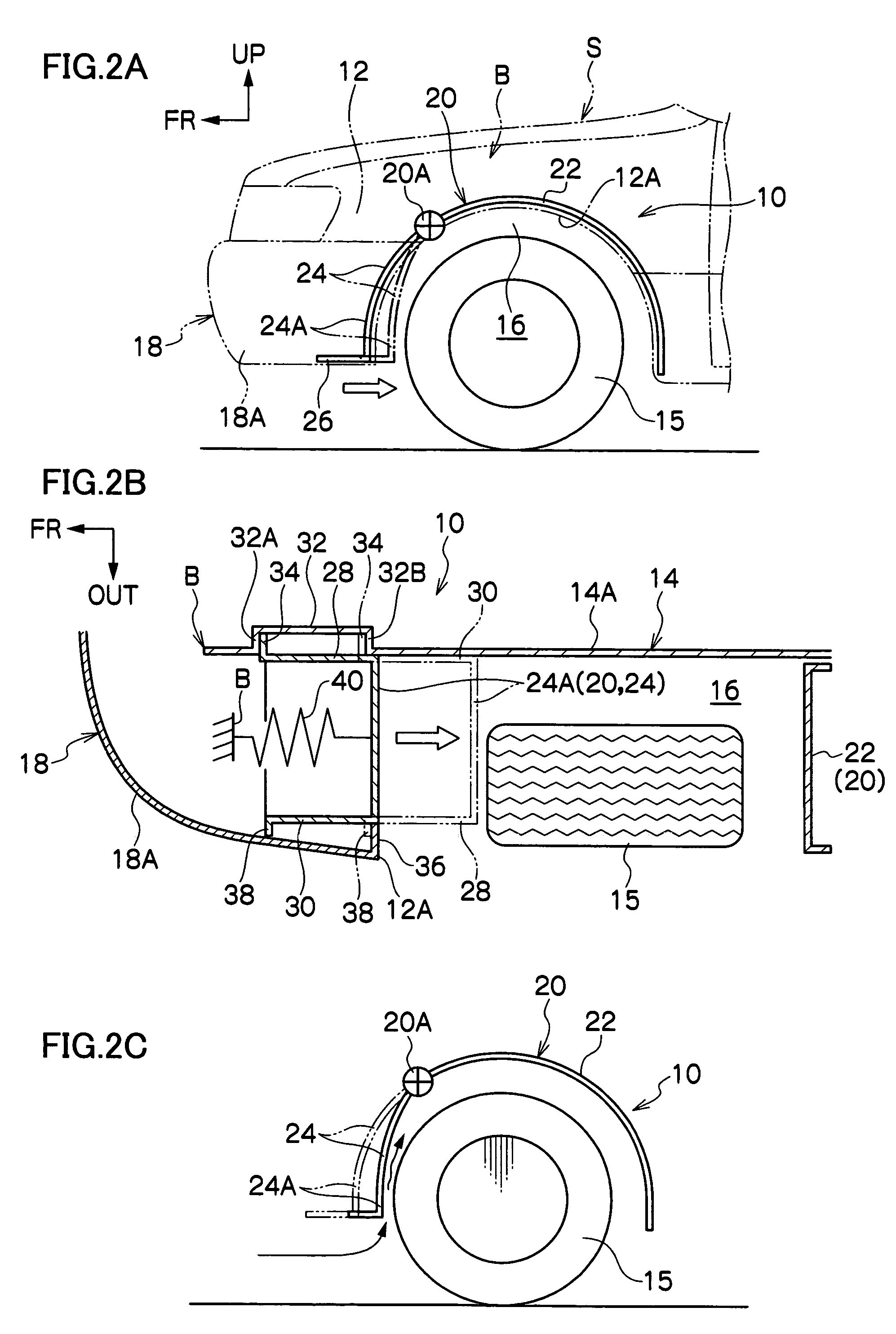
[0071]An aerodynamic device 45 for a vehicle relating to a second exemplary embodiment of the present invention is shown in FIG. 4 in a plan sectional view which corresponds to FIG. 2B. As shown in FIG. 4, the aerodynamic device 45 for a vehicle differs from the aerodynamic device 10 for a vehicle relating to the first exemplary embodiment with regard to the point that the aerodynamic device 45 for a vehicle has an extending / contracting inner side wall 46 and an extending / contracting outer side wall 48 instead of the inner side wall 28 and the outer side wall 30.
[0072]The extending / contracting inner side wall 46 and the extending / contracting outer side wall 48 are each formed in the shape of bellows. The rear ends thereof are connected to the movable liner portion 24, and the front end portions thereof are fixed to the vehicle body B. Further, the extending / contracting inner side wall 46 and the extending / contracting outer side wall 48 are not connected to the bottom wall portion 26...
third exemplary embodiment
[0075]An aerodynamic device 50 for a vehicle relating to a third exemplary embodiment of the present invention is shown in FIG. 5A in a side view corresponding to FIG. 2A. The aerodynamic device 50 for a vehicle is shown in FIG. 5B in a plan sectional view corresponding to FIG. 2B. As shown in FIGS. 5A and 5B, the aerodynamic device 50 for a vehicle differs from the aerodynamic device 10 for a vehicle relating to the first exemplary embodiment with regard to the point that traveling wind (positive pressure), which is introduced-in from an air guiding port 52 formed in the bumper cover 18A of the front bumper 18, is utilized. The other structures of the aerodynamic device 50 for a vehicle are the same as the corresponding structures of the aerodynamic device 10 for a vehicle.
[0076]In the automobile S equipped with the aerodynamic device 50 for a vehicle, as the automobile S travels, negative pressure is generated at the front portion of the wheel house 16, and air is introduced-in fr...
fourth exemplary embodiment
[0078]An aerodynamic device 55 for a vehicle relating to a fourth exemplary embodiment of the present invention is shown in FIG. 6 in a plan sectional view corresponding to FIG. 5B. As shown in FIG. 6, the aerodynamic device 55 for a vehicle differs from the aerodynamic device 50 for a vehicle relating to the third exemplary embodiment with regard to the point that a duct 56 which extends downward from the edge portion of the air guiding port 52 is provided.
[0079]The duct 56 concentratedly guides, to the front surface of the lower portion 24A of the movable liner portion 24, the traveling wind which is introduced-in from the air guiding port 52. In this way, as compared with the aerodynamic device 50 for a vehicle, the driving moment (arm) around the fixing / supporting portion 20A which is applied to the movable liner portion 24 becomes large, and the driving force of the lower portion 24A of the movable liner portion 24 due to the positive pressure increases. The other structures of...
PUM
 Abstract
Description
Claims
Application Information
 - R&D
- Intellectual Property
- Life Sciences
- Materials
- Tech Scout
- Unparalleled Data Quality
- Higher Quality Content
- 60% Fewer Hallucinations
Browse by: Latest US Patents, China's latest patents, Technical Efficacy Thesaurus, Application Domain, Technology Topic, Popular Technical Reports.
© 2025 PatSnap. All rights reserved.Legal|Privacy policy|Modern Slavery Act Transparency Statement|Sitemap|About US| Contact US: help@patsnap.com


