Charging apparatus and charging current detecting circuit thereof

a charging apparatus and charging current technology, applied in secondary cells, process and machine control, instruments, etc., can solve the problems of high cost of rail-to-rail operational amplifiers, insufficient input voltage (2 v) and high cost of operating amplifiers, etc., to achieve low cost, simple configuration, and low voltage loss

Active Publication Date: 2008-06-03
ALPS ALPINE CO LTD
View PDF7 Cites 0 Cited by
  • Summary
  • Abstract
  • Description
  • Claims
  • Application Information

AI Technical Summary

Benefits of technology

[0020]Accordingly, the present invention is designed to solve the above problems, and it is an object of the present invention to provide a charging apparatus and a charging current detecting circuit thereof, that is capable of realizing an electric circuit having minimized voltage loss by using an operational amplifier which is low in cost.
[0022]In addition, according to such a configuration, even when an operational amplifier of low cost is used, it is possible to supplement the voltage limited to the range of an input voltage of the operational amplifier by using a simple configuration, thereby suitably driving the operational amplifier. Further, since the ground of a system can be directly connected to the ground of a secondary battery, it is possible to realize an electric circuit with little voltage loss.
[0024]In addition, according to the above configuration, it is possible to constitute the auxiliary power means with a further simple configuration and low cost.
[0026]In addition, according to such a configuration, even when an operational amplifier of low cost is used, it is possible to supplement the voltage limited to the range of an input voltage of the operational amplifier by using a simple configuration, thereby suitably driving the operational amplifier. Further, since the ground of a system can be directly connected to the ground of a secondary battery, it is possible to implement an electric circuit with little voltage loss.

Problems solved by technology

As a result, the input voltage (2 V) is insufficient to drive the operational amplifier 9.
However, the rail-to-rail operational amplifier is high in cost (FIG. 3)

Method used


Image

  • Charging apparatus and charging current detecting circuit thereof
  • Charging apparatus and charging current detecting circuit thereof
  • Charging apparatus and charging current detecting circuit thereof

Examples


Embodiment Construction

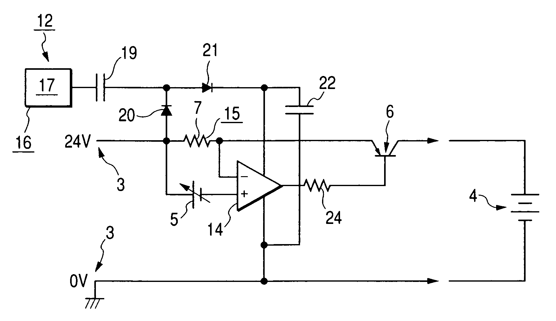
[0030]Hereinafter, an embodiment of a charging apparatus and a charging current detecting circuit thereof according to the present invention will be described in detail with reference to FIG. 1.

[0031]Further, the constituent elements corresponding to a conventional embodiment are denoted by the same reference numerals indicated in the conventional embodiment.

[0032]As shown in FIG. 1, a charging apparatus 12 according to the present embodiment comprises a power supply 3 for supplying a charging current to a secondary battery 4; a detecting resistor 7 disposed at the downstream side of the power supply 3 for detecting the charging current; and an operational amplifier 14 for applying a voltage from the power supply 3.

[0033]In the present embodiment, the detecting resistor 7 constituting a charging current detecting circuit 15 is disposed at a power voltage side (24 V side) of the downstream side of the power supply 3.

[0034]In addition, the charging apparatus 12 according to the presen...


PUM

PropertyMeasurementUnit
input voltageaaaaaaaaaa
power voltageaaaaaaaaaa

Abstract

A charging apparatus and a charging current detecting circuit thereof are disclosed in which it is possible to implement an electric circuit with little voltage loss by using an operational amplifier of low cost. A detecting resistor is disposed at the power voltage side of the downstream side of a power supply. The charging apparatus further includes an auxiliary power means for generating an auxiliary voltage to supplement the voltage limited to the range of an input voltage of the operational amplifier.

Description

[0001]This application claims the benefit of priority to Japanese Patent Application No. 2003-193097, herein incorporated by reference.BACKGROUND OF THE INVENTION[0002]1. Field of the Invention[0003]The present invention relates to a charging apparatus and a charging current detecting circuit thereof, and more specifically, to a charging apparatus and a charging current detecting circuit that charge a secondary battery by supplying a charging current from a power supply to the secondary battery.[0004]2. Description of the Related Art[0005]Generally, a charging current detecting circuit for detecting a charging current supplied from a power supply to a secondary battery is provided in a charging apparatus for charging the secondary battery.[0006]FIG. 2 shows an example of a charging apparatus 2, such as an AC adapter, comprising such a charging current detecting circuit 1.[0007]The charging apparatus 2 comprises a power supply 3 having a predetermined voltage (24 V in FIG. 2). By sup...

Claims


Application Information

Patent Timeline
Patent Type & Authority Patents(United States)
IPC IPC(8): H02J7/00H02J7/04H02J7/16G01R19/00G01R31/36G05F1/10G05F1/56H01M10/44H02J7/10
CPCH02J7/00
Inventor MATSUDA, SHOJI
Owner ALPS ALPINE CO LTD
Why Eureka
Try Eureka