
Continuous laminate fuse

a laminate fuse and fuse technology, applied in the field of power circuit interruption, can solve the problems of fuses producing about 50% of the power (watts) thermal loss inside the network protector enclosure, fuses with undesirable damage and blowing characteristics, and not allowing selective operation, etc., to achieve the effect of minimizing voltage loss, reducing power (watts) thermal loss, and uniform current flow

Inactive Publication Date: 2006-01-19
EATON CORP
View PDF4 Cites 10 Cited by
  • Summary
  • Abstract
  • Description
  • Claims
  • Application Information

AI Technical Summary

Benefits of technology

[0012] Preferably, the continuous laminate fuse is not soldered and employs uniform length laminates, as contrasted with a relatively small soldered link, in order to provide advantages in power (watts) thermal losses.
[0013] The fuse may be manufactured by employing a press welding technique. With press welding, the fuse resistance value is equal to that of a flat copper bar. As a result, voltage losses are minimized, thereby maintaining a uniform current flow. Furthermore, a consistent pocket is preferably provided for tin alloy to reside.

Problems solved by technology

However, such fuses produce about 50% of the power (watts) thermal losses inside a network protector enclosure.
However, such fuses have undesirable damage and blowing characteristics and do not permit selective operation with limiters.
The temperature required to braze the fuse assembly weakens the relatively thin fuse elements, thereby causing variability in both damage and blowing characteristics.

Method used


Image

  • Continuous laminate fuse
  • Continuous laminate fuse
  • Continuous laminate fuse

Examples


Embodiment Construction

[0030] As employed herein, the statement that two or more parts are “connected” or “coupled” together shall mean that the parts are joined together either directly or joined through one or more intermediate parts. Further, as employed herein, the statement that two or more parts are “attached” shall mean that the parts are joined together directly.

[0031] As employed herein, the term “fastener” shall expressly include, but not be limited to, any suitable fastening member(s) (e.g., without limitation, a threaded fastener; a non-threaded fastener; a removable fastener; a non-removable fastener; a bolt; a machine screw; a rivet; a soldered connection; an adhesive connection), which is employed such that two or more parts are connected or coupled together.

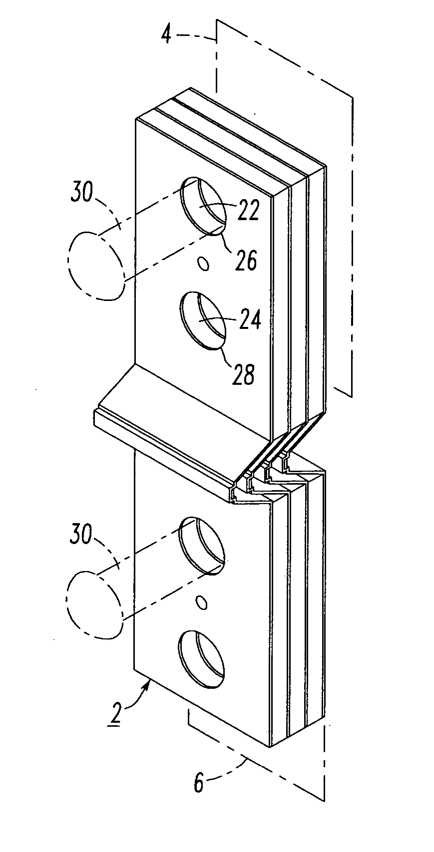
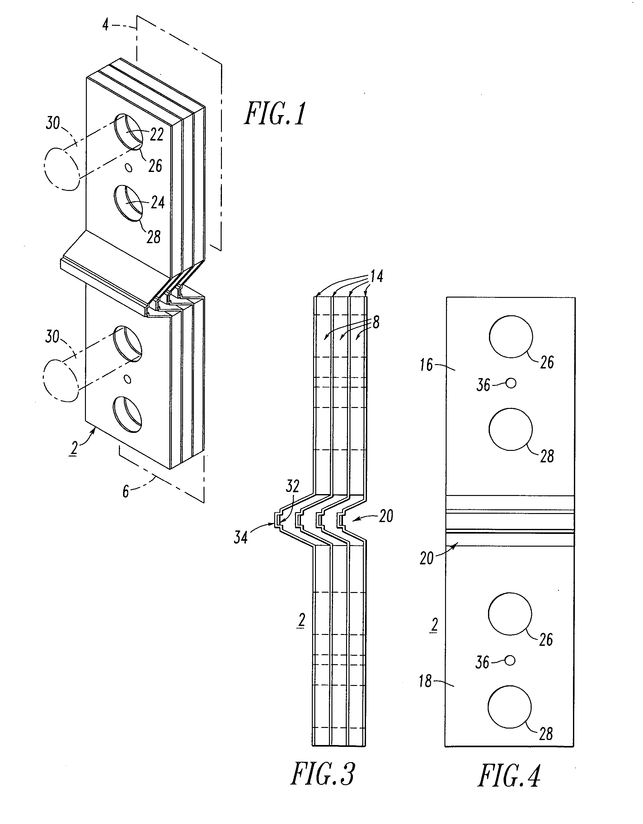
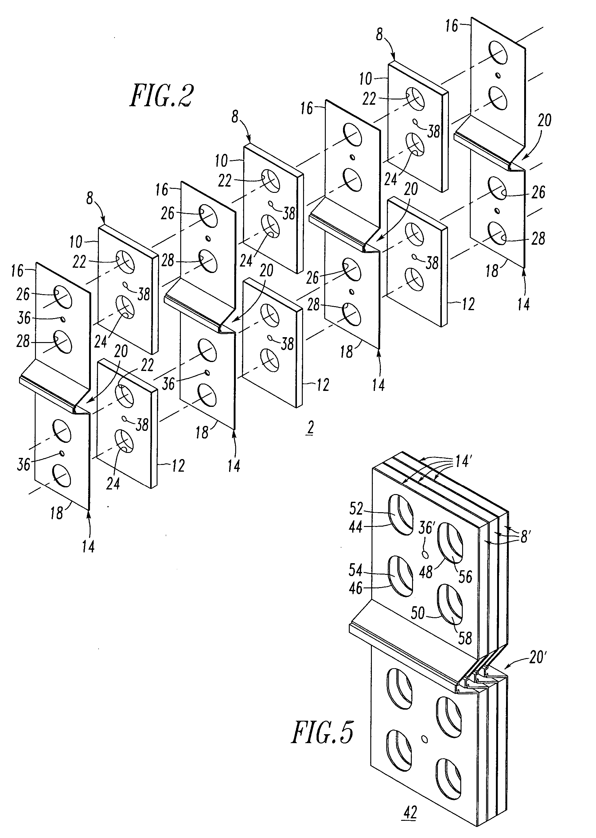
[0032] Referring to FIGS. 1-4, a low loss continuous laminate fuse 2 is shown. The fuse 2 is adapted for direct electrical and mechanical connection between a first low voltage power bus 4 (shown in phantom line drawing in FIG. 1) and...


PUM


Abstract

A fuse is adapted for electrical connection between a first low voltage power bus and a second low voltage power bus. The fuse includes one or more pairs of first and second spacer laminations. The first and second spacer laminations have a first area. The fuse also includes a plurality of fuse element laminations, each of which includes a first portion laminated to the first spacer lamination of one or two of the pairs, a second portion laminated to the second spacer lamination of the one or two of the pairs, and a third portion disposed between the first and second portions and intermediate the first and second spacer laminations of the one or two of the pairs. The first and second portions of the fuse element laminations have a second area, which is about equal to the first area.

Description

BACKGROUND OF THE INVENTION [0001] 1. Field of the Invention [0002] The present invention relates to power circuit interruption and, more particularly, to fuses providing circuit interruption for low voltage power busses. [0003] 2. Background Information [0004] Load side fuses of various designs are used in network protectors for underground power distribution. The primary purpose of these fuses is to act as a back-up to the network protector in the event of a malfunction thereof. Such a fuse coordinates with the network protector and should not blow on a network feeder fault before the network protector trips. However, if the network protector does not timely trip open, then the fuse must blow in a reasonable time in order to prevent transformer damage. [0005] Copper Z, copper Y and S fuse links are designed to handle relatively high currents (e.g., about 800 A to about 6 kA) and low voltage (e.g., up to about 600 VACRMS). Typically, the fuses are made of pure copper and are silver...

Claims


Application Information

Patent Timeline
Patent Type & Authority Applications(United States)
IPC IPC(8): H02H5/04
CPCH01H85/044H01H85/201H01H85/12H01H85/08
Inventor FAULKNER, MARK A.JUR, ARTHUR J.BRADBERRY, SHANNON C.BRANDT, DOUGLAS M.
Owner EATON CORP
Learn More