
Electroluminescence display and method for driving the same

a technology of electroluminescence display and display panel, which is applied in the direction of semiconductor devices, instruments, electrical apparatus, etc., can solve the problems of electrical characteristics that can vary between pixels, and achieve the effects of preventing a bright degradation of display panel, preventing a decrease in brightness, and preventing a decrease in the brightness of the electroluminescence display

Active Publication Date: 2019-01-03
LG DISPLAY CO LTD
View PDF2 Cites 8 Cited by
  • Summary
  • Abstract
  • Description
  • Claims
  • Application Information

AI Technical Summary

Benefits of technology

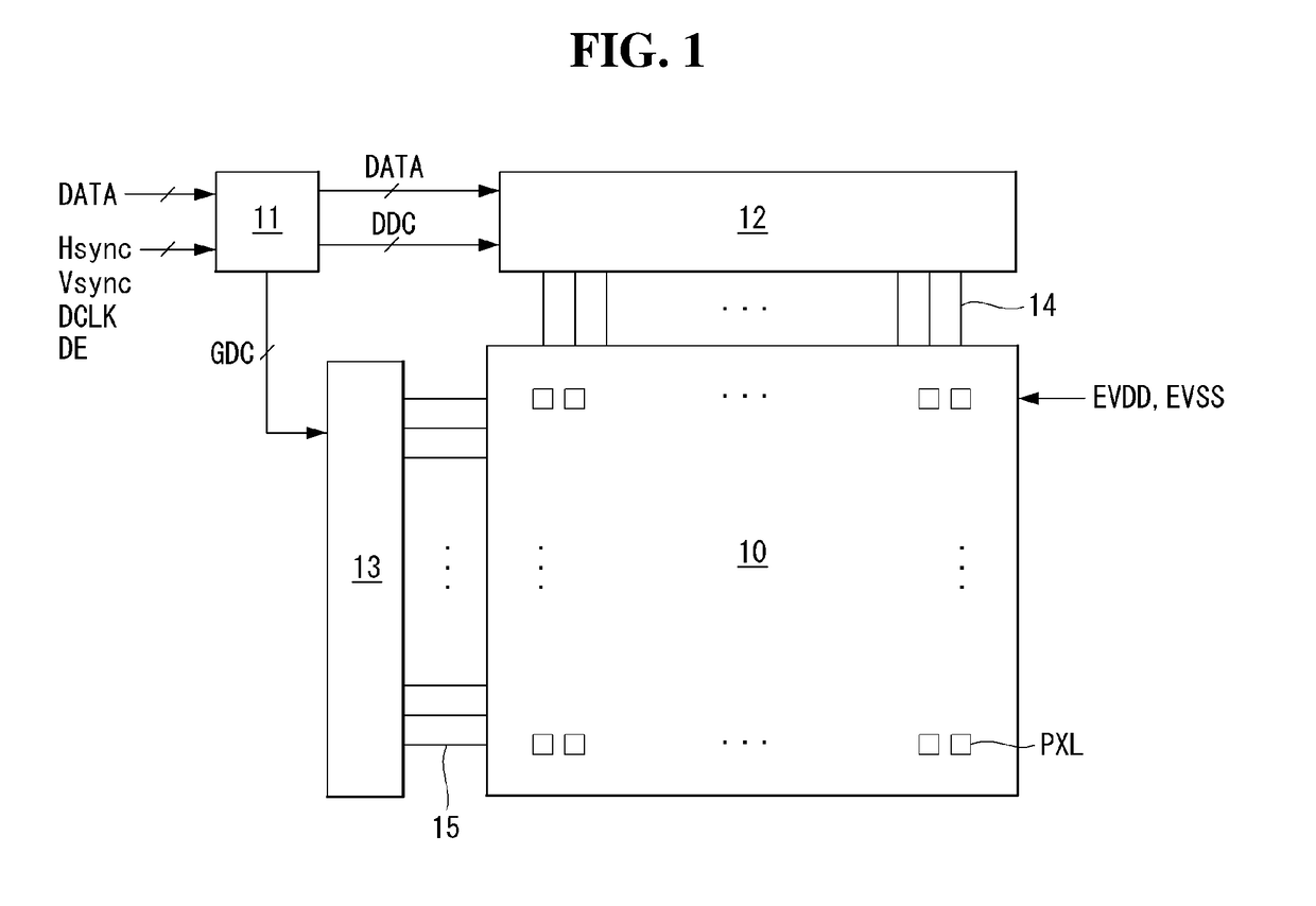
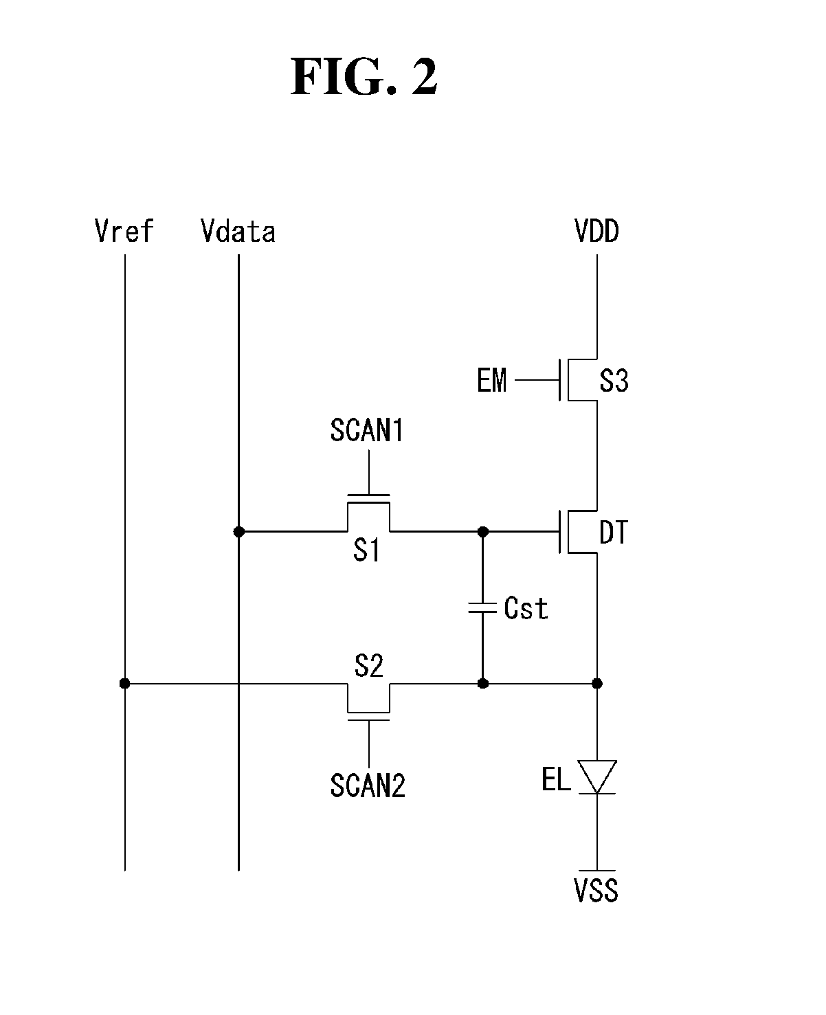
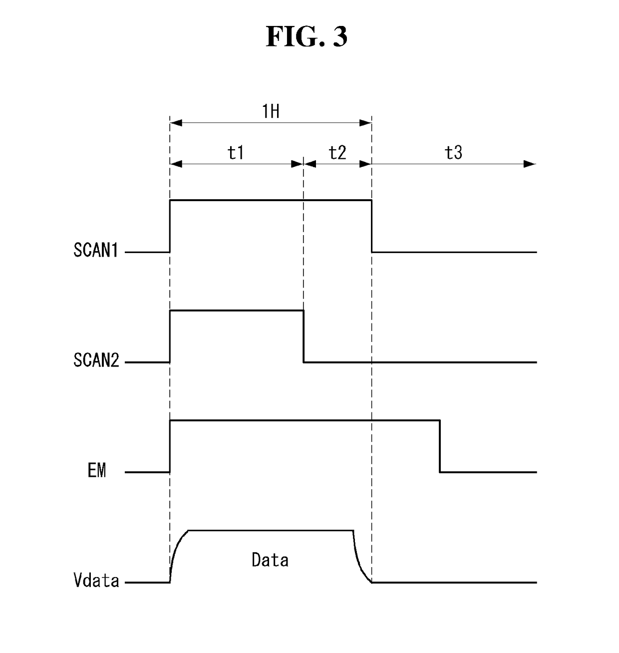
This patent is for an electroluminescence display that can compensate for the characteristics of the driving TFT in each pixel. The display includes a display panel with a plurality of pixels connected to data lines and gate lines. Each pixel includes a gate drive circuit, a data drive circuit, a driving TFT, and first, second, and third switching TFTs. The display is driven by switching between different modes to compensate for the driving TFT and prevent bright degradation of the display panel. This compensation is performed by writing data to the gate of the driving TFT and applying an initial voltage. After compensation, a data voltage is applied to achieve brightness uniformity and prevent a decrease in brightness of the display. The invention aims to improve the brightness and minimize voltage loss by compensating for the characteristics of the driving TFT and writing data after compensation is complete.

Problems solved by technology

However, the electrical characteristics can vary between pixels, due to various causes including process variation, temporal change, etc.

Method used


Image

  • Electroluminescence display and method for driving the same
  • Electroluminescence display and method for driving the same
  • Electroluminescence display and method for driving the same

Examples


Embodiment Construction

[0035]Reference will now be made in detail aspects of the disclosure, examples of which are illustrated in the accompanying drawings.

[0036]Various aspects and features of the present disclosure and methods of accomplishing them may be understood more readily by reference to the following detailed descriptions of exemplary aspects and the accompanying drawings. The present disclosure may, however, be embodied in many different forms and should not be construed as being limited to the exemplary aspects set forth herein. Rather, these exemplary aspects are provided so that this disclosure will be thorough and complete and will fully convey the concept of the present disclosure to those skilled in the art, and the present disclosure is defined by the appended claims.

[0037]The shapes, sizes, proportions, angles, numbers, etc. shown in the figures to describe the exemplary aspects of the present disclosure are merely examples and not limited to those shown in the figures. Like reference n...


PUM


Abstract

Provided is an electroluminescence display comprising a display panel where a plurality of pixels connected to a plurality of data lines and a plurality of gate lines are arranged. Each pixel comprises: a driving TFT that controls the current in a light-emitting element EL in response to a data voltage applied to a gate; and switching TFTs that supply a high-level power supply voltage to the driving TFT in response to a gate-on voltage of an emission signal and control signals applied to the source and drain of the driving TFT. The electroluminescence display switches between first and second modes, the first mode being a mode in which data writing and driving TFT characteristic compensation are performed within 1 horizontal period 1H by applying a data voltage to the gate of the driving TFT, and the second mode being a mode in which data writing is performed within the 1 horizontal period by applying an initial voltage to the gate of the driving TFT and applying the data voltage upon completion of the compensation of the driving TFT characteristics.

Description

CROSS REFERENCE TO RELATED APPLICATION[0001]This application claims the benefit of Korean Patent Application No. 10-2017-0083472 filed on Jun. 30, 2017, which is incorporated herein by reference in its entirety for all purposes as if fully set forth hereinBACKGROUNDField of the Disclosure[0002]The present disclosure relates to a display device, more particularly, to an electroluminescence display and a method for driving the same.Description of the Background[0003]Electroluminescence displays can be classified into inorganic light-emitting displays and organic light-emitting displays depending on the material of an emission layer. Of these, an active-matrix organic light emitting display comprises organic light-emitting diodes (hereinafter, “OLED”), which are typical light-emitting diodes that emit light themselves, and has advantages of fast response time, high luminous efficiency, high brightness, and wide viewing angle.[0004]An OLED of an organic light-emitting display comprises ...

Claims


Application Information

Patent Timeline
Patent Type & Authority Applications(United States)
IPC IPC(8): H01L27/32H01L27/12G09G3/3258G09G3/3233
CPCH01L27/3276H01L27/1214G09G3/3258G09G3/3233G09G2300/0819G09G2310/0251G09G2310/0262G09G2310/065G09G2320/0233G09G2320/045G09G2300/043G09G2300/0842G09G2230/00H10K59/131
Inventor CHO, HYUNGNYUCKSUK, JUNGYOUP
Owner LG DISPLAY CO LTD
Learn More