
Method and system for geo-referencing and visualization of detected contaminants

a georeferencing and contamination technology, applied in chemical methods analysis, instruments, reradiation, etc., can solve the problems of high probability of contamination scene disruption and inability to keep track of already surveyed areas, and achieve the effect of reducing the difficulty of re-sealing and re-sealing

Active Publication Date: 2008-06-03
PERATON INC
View PDF14 Cites 33 Cited by
  • Summary
  • Abstract
  • Description
  • Claims
  • Application Information

AI Technical Summary

Problems solved by technology

Thus, the chance that the contaminated scene can become disrupted is high.
Further, for large search / detection missions that can include walls, floors, and ceilings, the task of keeping track of already surveyed areas becomes quickly intractable.
No substance detection system is heretofore known that provides for real-time AR display of a scene as it is being scanned for contaminations.

Method used


Image

  • Method and system for geo-referencing and visualization of detected contaminants
  • Method and system for geo-referencing and visualization of detected contaminants
  • Method and system for geo-referencing and visualization of detected contaminants

Examples


Embodiment Construction

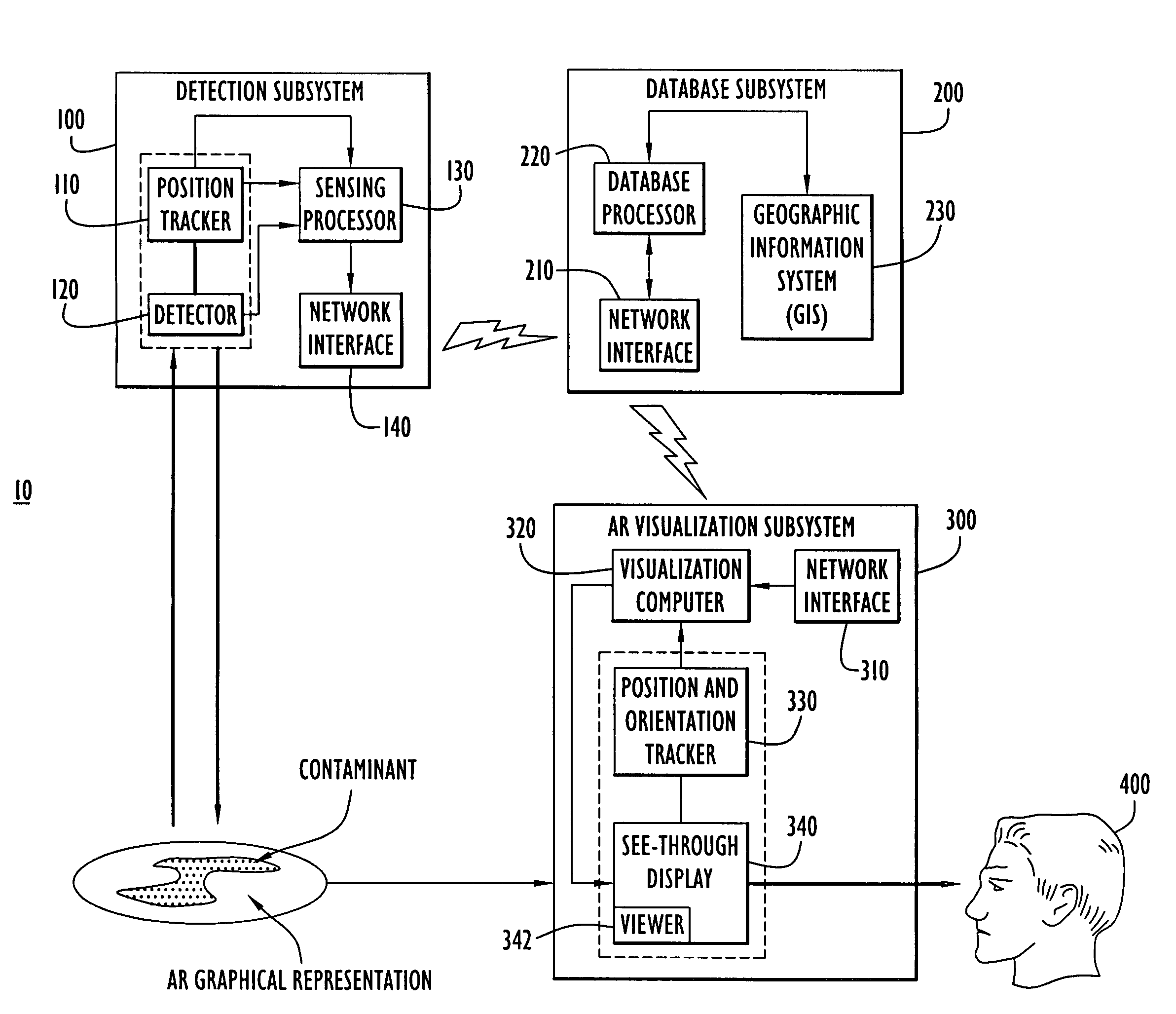
[0009]Referring first to FIG. 1, a system according to one embodiment of the invention is shown at reference 10 and comprises a detection subsystem or module 100, a database subsystem or module 200 and an augmented reality (AR) visualization subsystem or module 300. The detection subsystem 100 detects a substance and generates first data representing at least one characteristic of the substance. The detection subsystem 100 also determines positional information indicating where the substance is detected and generates second data representing the position of the detected substance. Furthermore, the detection subsystem 100 may generate positional information that indicates where the detection subsystem 100 has already scanned for substances (regardless of whether a substance has been detected) within a given area. The first and second data, which may be referred to as geo-referenced data, are supplied to the database subsystem 200. The database subsystem 200 logs the geo-referenced da...


PUM

PropertyMeasurementUnit
real-timeaaaaaaaaaa
compositionaaaaaaaaaa
distanceaaaaaaaaaa

Abstract

A system and method are provided for visualizing a scene that is monitored for substance contamination. The scene is scanned with a substance detector to detect a substance, such as a harmful chemical or biological substance. The position of the substance is determined. Graphical element data that represents the detected substance in the scene is generated. A displayed view of the scene is augmented with the graphical element data based on the position of the detected substance to show the detected substance in the view of the scene and provide the user with the location and type of detected substance shown with reference to the environment.

Description

FIELD OF THE INVENTION[0001]The present invention relates to displaying information pertaining to detected substances, such as at a contaminated scene.BACKGROUND OF THE INVENTION[0002]In the field of chemical or biological sensing or detecting, it is desirable to quickly detect substances at a contaminated scene and report information about the substances in order to prevent others from coming into contact or influence with the detected substance. There are standoff chemical detectors heretofore known that display information associated with the detection process independently from the scene where the chemicals are detected.[0003]There are many shortcomings associated with the above-mentioned devices. Unless the contaminated scene is properly marked, a user carrying and controlling the detection equipment is the only one that can confirm the presence or absence of a substance at a specific location by performing a real-time measurement at the given location. The user carrying and co...

Claims


Application Information

Patent Timeline
Patent Type & Authority Patents(United States)
IPC IPC(8): G01N21/17
CPCG01N21/94
Inventor BAILLOT, YOHANPONSARDIN, PATRICK LOUIS
Owner PERATON INC
Learn More