Cylindrical lamp employing internal reflector

Inactive Publication Date: 2008-06-10
OSRAM SYLVANIA INC
View PDF9 Cites 0 Cited by
  • Summary
  • Abstract
  • Description
  • Claims
  • Application Information

AI Technical Summary

Benefits of technology

[0004]It is another object of the invention to enhance the operation of lamps.

Problems solved by technology

Increasing the light output of any given lamp is a constant effort.
While the latter technique works, it also increases the cost of operation.
U.S. Pat. No. 3,983,513, issued Sep. 28, 1976, suggests that this can be accomplished by providing a reflective coating on the inside of a portion of large spherical or hemispherical lamp envelopes; however, providing internal coatings on lamp envelopes is a difficult and costly endeavor.
Also, such a technique does not readily adapt to cylindrical lamp envelopes.

Method used


Image

  • Cylindrical lamp employing internal reflector
  • Cylindrical lamp employing internal reflector

Examples


Embodiment Construction

[0008]For a better understanding of the present invention, together with other and further objects, advantages and capabilities thereof, reference is made to the following disclosure and appended claims taken in conjunction with the above-described drawings.

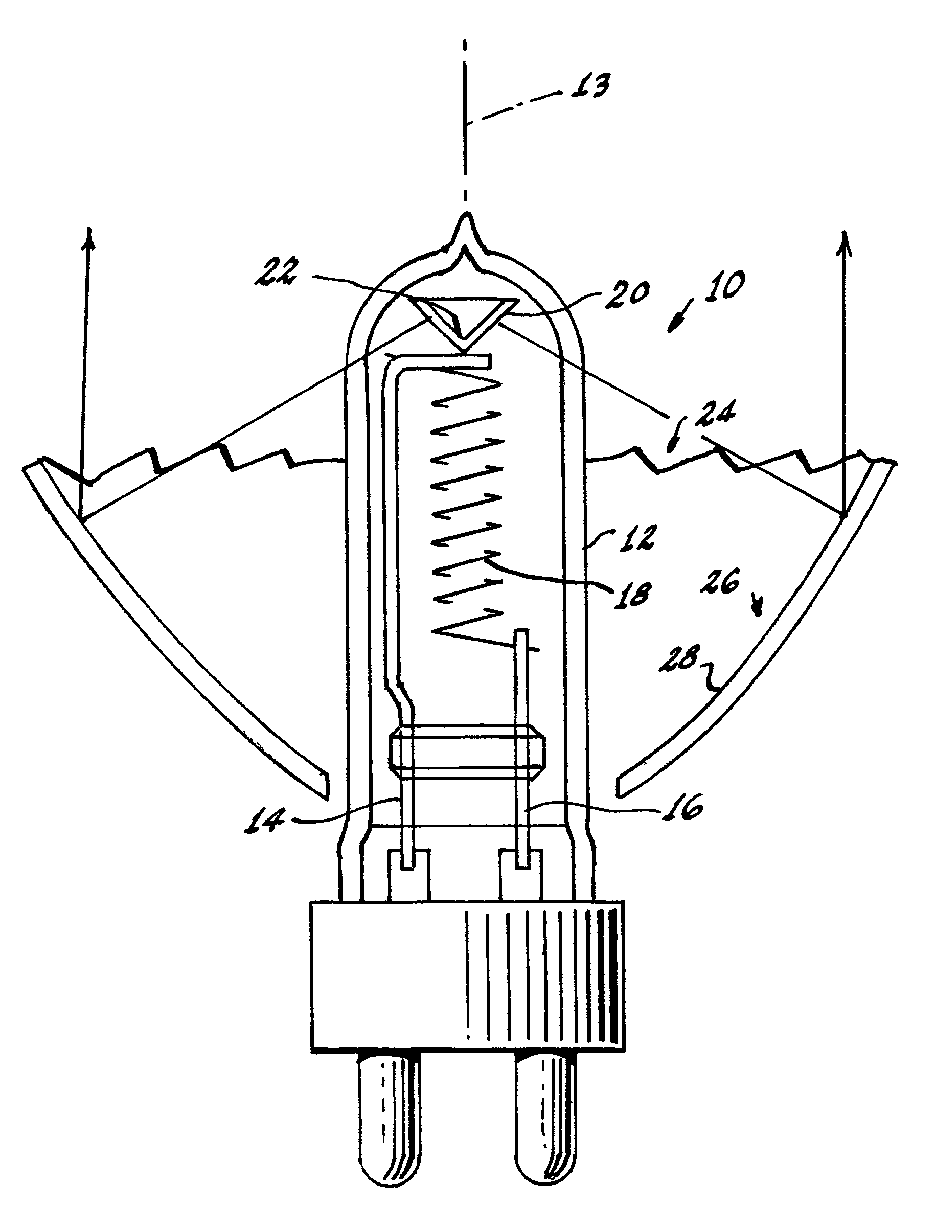
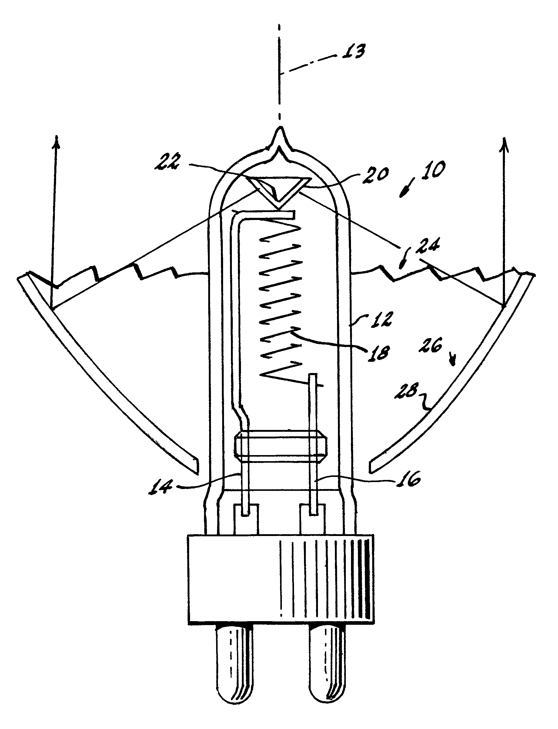
[0009]Referring now to the drawing with greater particularity, there is shown a lamp 10 that can be a lamp for operating on a tungsten-halogen cycle. The lamp 10 comprises an hermetically sealed, cylindrical envelope 12 of a suitable transparent material such as glass, arrayed about a longitudinal axis 13. Two filament supports 14, 16 are sealed in the envelope and a filament 18 is fixed between them. As shown in the FIGURE the filament 18 is vertical; however, this is exemplary, and horizontal filaments or multiple filaments can also be employed. An internal reflector 20 is fixed in the top portion of the lamp, as by welding to one of the supports, for example 14. The internal reflector 20 directs light emitted from the filament...


PUM


Abstract

A lamp (10) comprising an hermetically sealed, cylindrical envelope (12) arrayed about a longitudinal axis (13); two filament supports (14, 16) sealed in the envelop; a filament (18) fixed between the filaments supports; and an internal reflector (20) in the envelope for directing light emitted from the filament outwardly from the envelope.

Description

TECHNICAL FIELD[0001]This invention relates generally to lamps and more particularly to lamps having increased light output.BACKGROUND ART[0002]Increasing the light output of any given lamp is a constant effort. Beyond gaining small advantages by tweaking the filament or the environment in which the filament operates it is generally necessary supply more power, that is, increase the wattage. While the latter technique works, it also increases the cost of operation. Therefore, it is desirable to increase the light out put of lamps without increasing the wattage. U.S. Pat. No. 3,983,513, issued Sep. 28, 1976, suggests that this can be accomplished by providing a reflective coating on the inside of a portion of large spherical or hemispherical lamp envelopes; however, providing internal coatings on lamp envelopes is a difficult and costly endeavor. Also, such a technique does not readily adapt to cylindrical lamp envelopes.DISCLOSURE OF INVENTION[0003]It is, therefore, an object of the...

Claims


Application Information

Patent Timeline
IPC IPC(8): H01K1/26H01J5/16H01J61/40H01K7/02
CPCH01J61/025
Inventor GARCIA, CEFERINO H.
Owner OSRAM SYLVANIA INC
Why Eureka
Try Eureka