Intermediate casing of a turbine engine with seals at the arm/shroud interface

A technology for turbine engines and intermediate casings, which is applied in the direction of machines/engines, engine components, gas turbine devices, etc., and can solve problems such as instability, increasing the shield gap between the arm and the intermediate casing, and affecting component performance.

Active Publication Date: 2021-09-10
SAFRAN AIRCRAFT ENGINES SAS
View PDF11 Cites 0 Cited by
  • Summary
  • Abstract
  • Description
  • Claims
  • Application Information

AI Technical Summary

Problems solved by technology

[0005] Eliminating corrosion increases the clearance between the arm and the shroud of the intermediate housing, which affects the quality of the cont

Method used


Image

  • Intermediate casing of a turbine engine with seals at the arm/shroud interface
  • Intermediate casing of a turbine engine with seals at the arm/shroud interface
  • Intermediate casing of a turbine engine with seals at the arm/shroud interface

Examples


Embodiment Construction

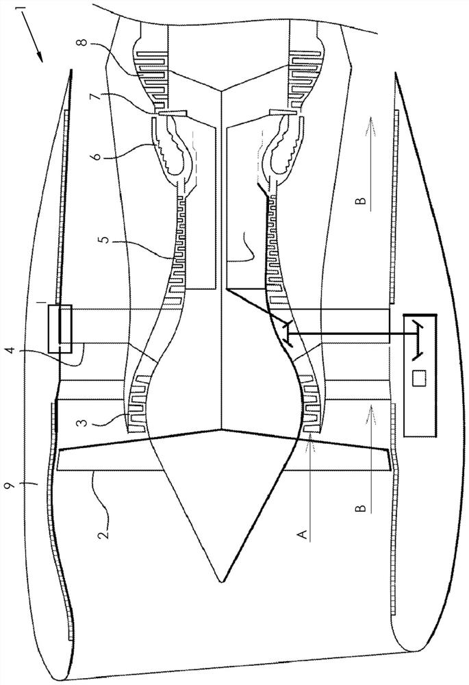
[0043] figure 1 A turbofan engine 1 is schematically shown. In this figure a circular relief I is shown, which is located in the area of ​​interest in which the invention is applied. In downstream direction, the turbine engine 1 comprises a blower 2 , a low-pressure compressor 3 , an intermediate casing 4 , a high-pressure compressor 5 , a combustion chamber 6 , a high-pressure turbine 7 and a low-pressure turbine 8 .

[0044] The turbine engine 1 also includes a nacelle 9 . The air entering the turbine engine 1 is divided into a primary air flow (arrow A) and a secondary air flow (arrow B); the primary air flow is inside the low pressure compressor 3 and high pressure compressor 5 towards the combustion chamber 6 and then passes through the high pressure turbine 7 and The low pressure turbine 8 circulates; the secondary air flow bypasses the compressor 3 , the combustor 6 and the turbine 7 .

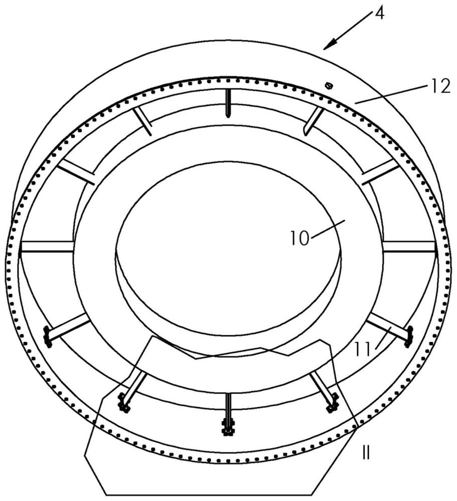
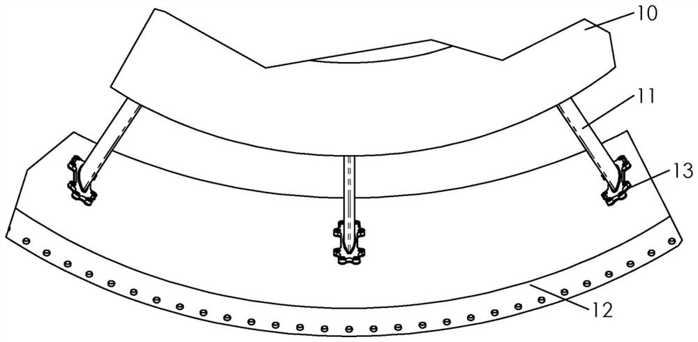
[0045] figure 2 is a simplified schematic diagram of an intermediate casing 4 ...


PUM

PropertyMeasurementUnit
Thicknessaaaaaaaaaa
Thicknessaaaaaaaaaa
Thicknessaaaaaaaaaa

Abstract

The invention relates to an intermediate turbine casing comprising at least one central hub and shroud (12) positioned concentrically to each other and mechanically connected by structural arms (11), said casing It comprises at least one sealing member (13) fixed between the shroud (12) and the structural arm (11), said sealing member (13) comprising at least one metal core and a seal.

Description

technical field [0001] The present invention relates generally to the field of turbofan engines, and more particularly to the field of intermediate casings provided with such turbine engines. The prior art concerning intermediate casings of turbine engines can be explained with reference to patents FR2013 / 3010154 and FR2010 / 2968364. [0002] The invention relates to a sealing element provided on such an intermediate housing, capable of restoring the contact geometry between the arms of the housing and its shroud when the associated shroud is machined, which results in an arm / shield Material loss at the shield interface. Background technique [0003] Current turbojet turbofan engines generally comprise a fan casing with an intermediate casing extension in downstream direction. [0004] When the shroud of the intermediate casing of these turbine engines is disassembled in a repair shop, corrosion can be detected on the contact area of ​​this part with the arm of the intermed...

Claims


Application Information

Patent Timeline
IPC IPC(8): F01D11/00F01D25/16F02C7/28
CPCF01D11/005F01D25/162F02C7/28F05D2230/80F05D2240/55F01D5/005F01D5/143F01D9/023F01D25/24F01D25/28F05D2230/642
Inventor 西蒙·皮埃尔·克劳德·沙博尼耶帕特里克·让-路易斯·雷格赫扎朱利恩·罗塞特扬·克里斯托夫·莫里斯·萨拉辛
Owner SAFRAN AIRCRAFT ENGINES SAS
Why Eureka
Try Eureka