System and method for constant bandwidth DC offset correction in an amplifier

a constant bandwidth, amplifier technology, applied in the field of circuits, can solve the problems of inability to adjust the bandwidth of the feedback loop, inability to saturate the active amplifier stage, random dc offset voltage of direct conversion receivers, etc., and achieve the effect of constant bandwidth

Active Publication Date: 2008-06-10
SKYWORKS SOLUTIONS INC
View PDF3 Cites 16 Cited by
  • Summary
  • Abstract
  • Description
  • Claims
  • Application Information

AI Technical Summary

Problems solved by technology

However, direct conversion receivers typically suffer from random DC offset voltages which may be caused by local oscillator self mixing and DC offsets present in the active amplifier stages.
These random DC offset voltages can undesirably saturate the active amplifier stages.
However, to avoid cancellation of any desired input signals, the feedback loop must be band-limited.
As such, in applications where the gain of the amplifier stage is continuously varied by an analog control signal, the conventional feedback loop cannot maintain a constant bandwidth to provide proper DC offset correction.

Method used


Image

  • System and method for constant bandwidth DC offset correction in an amplifier
  • System and method for constant bandwidth DC offset correction in an amplifier
  • System and method for constant bandwidth DC offset correction in an amplifier

Examples


Embodiment Construction

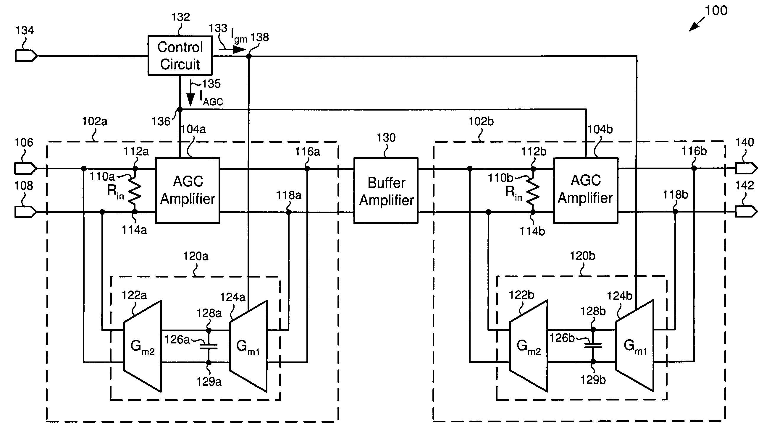
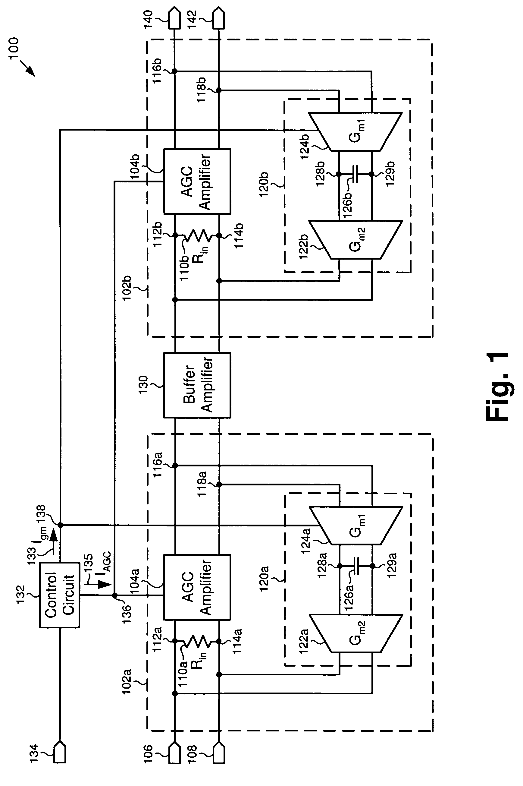
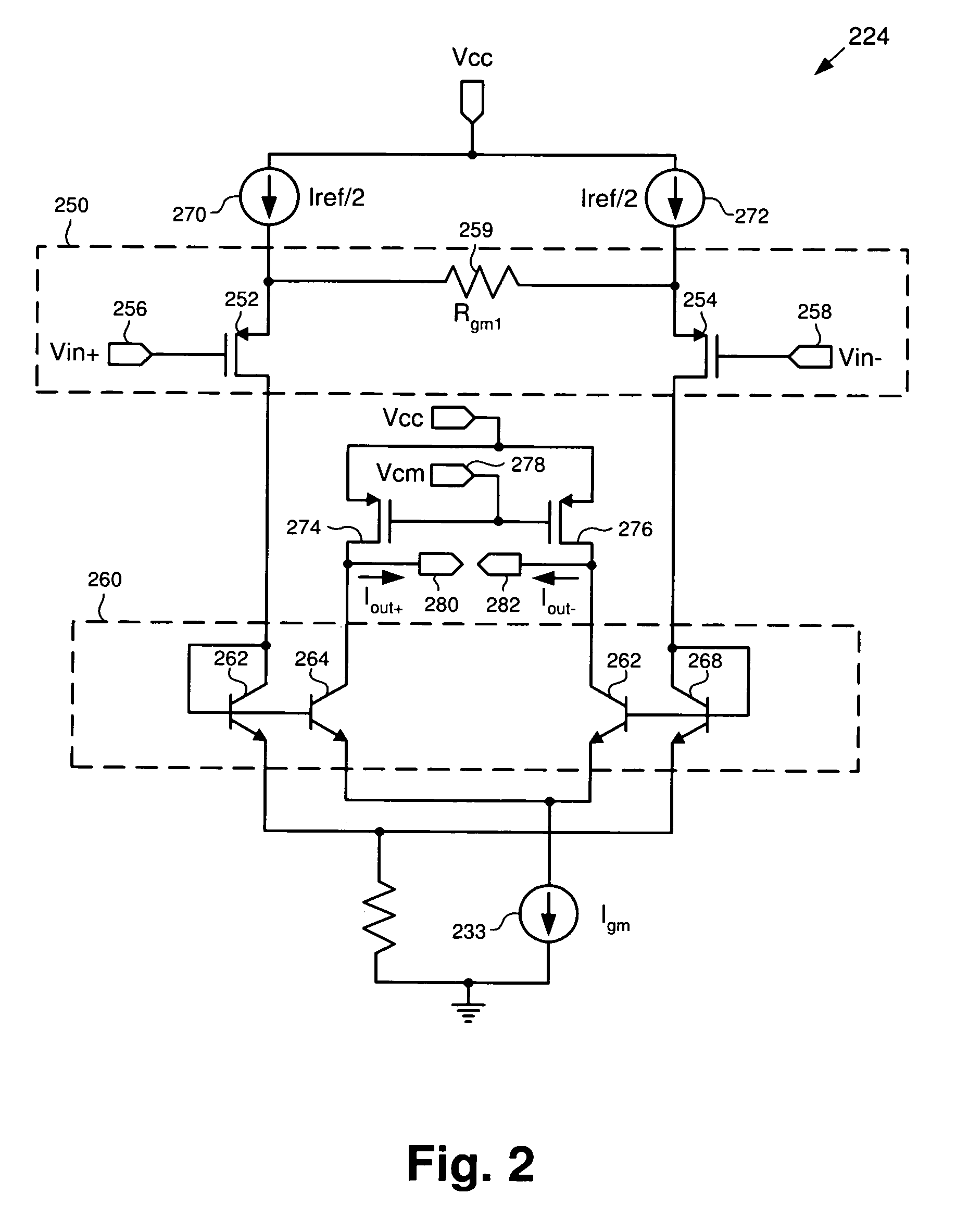
[0016]The present invention is directed to a system and method for constant bandwidth DC offset correction in an amplifier. The following description contains specific information pertaining to the implementation of the present invention. One skilled in the art will recognize that the present invention may be implemented in a manner different from that specifically discussed in the present application. Moreover, some of the specific details of the invention are not discussed in order not to obscure the invention. The specific details not described in the present application are within the knowledge of a person of ordinary skill in the art.

[0017]The drawings in the present application and their accompanying detailed description are directed to merely exemplary embodiments of the invention. To maintain brevity, other embodiments of the invention which use the principles of the present invention are not specifically described in the present application and are not specifically illustra...


PUM


Abstract

According to one embodiment, a system for constant bandwidth DC offset correction in an amplifier includes a number of amplifier stages having an input and an output coupled together in series. The system for constant bandwidth DC offset correction further includes a number of DC offset correction feedback loops which include a variable gain transconductor coupled to an integration capacitor further coupled to a fixed gain transconductor. Each of the DC offset correction feedback loops are coupled to the input and output of each of the number of amplifier stages. The transconductance of the variable gain transconductor in each of the number of DC correction feedback loops is varied in relation to a gain of the number of amplifier stages, such that the DC offset correction feedback loops provide DC offset correction while maintaining a constant bandwidth.

Description

BACKGROUND OF THE INVENTION[0001]1. Field of the Invention[0002]The present invention is generally in the field of circuits. More specifically, the invention is in the field of amplifier circuits.[0003]2. Background Art[0004]Direct conversion receiver architectures are desirable in radio designs because they are able to down-convert an incoming Radio Frequency (“RF”) signal to an Intermediate Frequency (“IF”) signal, thereby eliminating the need for external RF / IF filter blocks and consequently reducing the cost of the receiver. However, direct conversion receivers typically suffer from random DC offset voltages which may be caused by local oscillator self mixing and DC offsets present in the active amplifier stages. These random DC offset voltages can undesirably saturate the active amplifier stages.[0005]In order to reduce the DC offset voltages, a feedback loop is typically used around the active amplifier stage to suppress the DC offset voltages. A conventional feedback loop ope...

Claims


Application Information

Patent Timeline
Patent Type & Authority Patents(United States)
IPC IPC(8): H03F1/02
CPCH03F3/4508H03F3/45197H03F2203/45008
Inventor RIPLEY, DAVID S.
Owner SKYWORKS SOLUTIONS INC
Why Eureka
Try Eureka