Packet discard point probing method and device

a point probing and point-to-point technology, applied in the field of package discard point probing method and device, can solve the problems of high labor cost and temporal cost of setting, operating and measuring two devices, and the failure to recover, so as to reduce time, cost and labor.

Active Publication Date: 2008-06-10
FUJITSU LTD
View PDF6 Cites 5 Cited by
  • Summary
  • Abstract
  • Description
  • Claims
  • Application Information

AI Technical Summary

Benefits of technology

[0012]It is accordingly an object of the present invention to provide a packet discard point probing method and device which can specify a discard point before and after an L2 switch, a hub, a LAN-TA (LAN terminal adaptor), or the like which is a relay device operative in the layer 2 without requiring numerous hosts and which can reduce time, cost, and labor until a recovery from a fault.
[0026]Namely, a probing packet (fragment ping request packet) having a size large enough to cause an IP fragment is transmitted from the probing terminal to a probed terminal, so that the sequence number and the arrival interval of its response packet (fragment ping response packet) are observed by the probing terminal, thereby enabling whether or not the packet discard has occurred in the high speed section of the transmission line in the down direction to be specified. This takes advantage that the fragment ping request packet is once assembled at the probed terminal and this assembled packet is again fragmentated to be returned as a fragment response packet.
[0028]Here, the probing packet is not used as mentioned above, but a packet for TCP data communication such as file transfer actually communicated between terminals is used, so that the TCP sequence number and the arrival interval of a data receiving packet are observed by a data receiving terminal, thereby enabling whether the packet discard has occurred in the high speed section or the low speed section of the transmission line in the up direction (TCP data transfer direction) to be specified.
[0033]Therefore, the number of packets sequentially transmitted at one time from the transmitting terminal or the probing terminal is set to a small number, that is e.g. periodical and sequential communication is performed at transmission intervals, or the probing packet is sequentially transmitted, whereby the buffer overflow in the relay device or the like is prevented from occurring, which makes the packet discard hard to occur.
[0054](1) A packet discard section under the layer 2 can be specified from a location on one side in a short time;
[0055](2) While in the conventional technology persons ran to both locations and performed various tests / data analyses for specifying the packet discard point by CE / SE or the like, the time, labor costs, and business trip costs can be greatly reduced in the present invention;

Problems solved by technology

As a result, there has been a problem that much time and cost are required until the fault recovers.
Also, there has been a problem that labor cost and temporal cost for setting, operating, and measuring two devices are expensive in the packet capture probing method.
Moreover, there has been a problem that a capture device is required, and in many cases there is a restriction for setting the device (e.g. probing is disabled in a carrier line).

Method used


Image

  • Packet discard point probing method and device
  • Packet discard point probing method and device
  • Packet discard point probing method and device

Examples


operational embodiment (1) (determination by sequential transmission of packets between two terminals : figs.5-8)

Operational Embodiment (1) (Determination by Sequential Transmission of Packets Between Two Terminals: FIGS. 5-8)

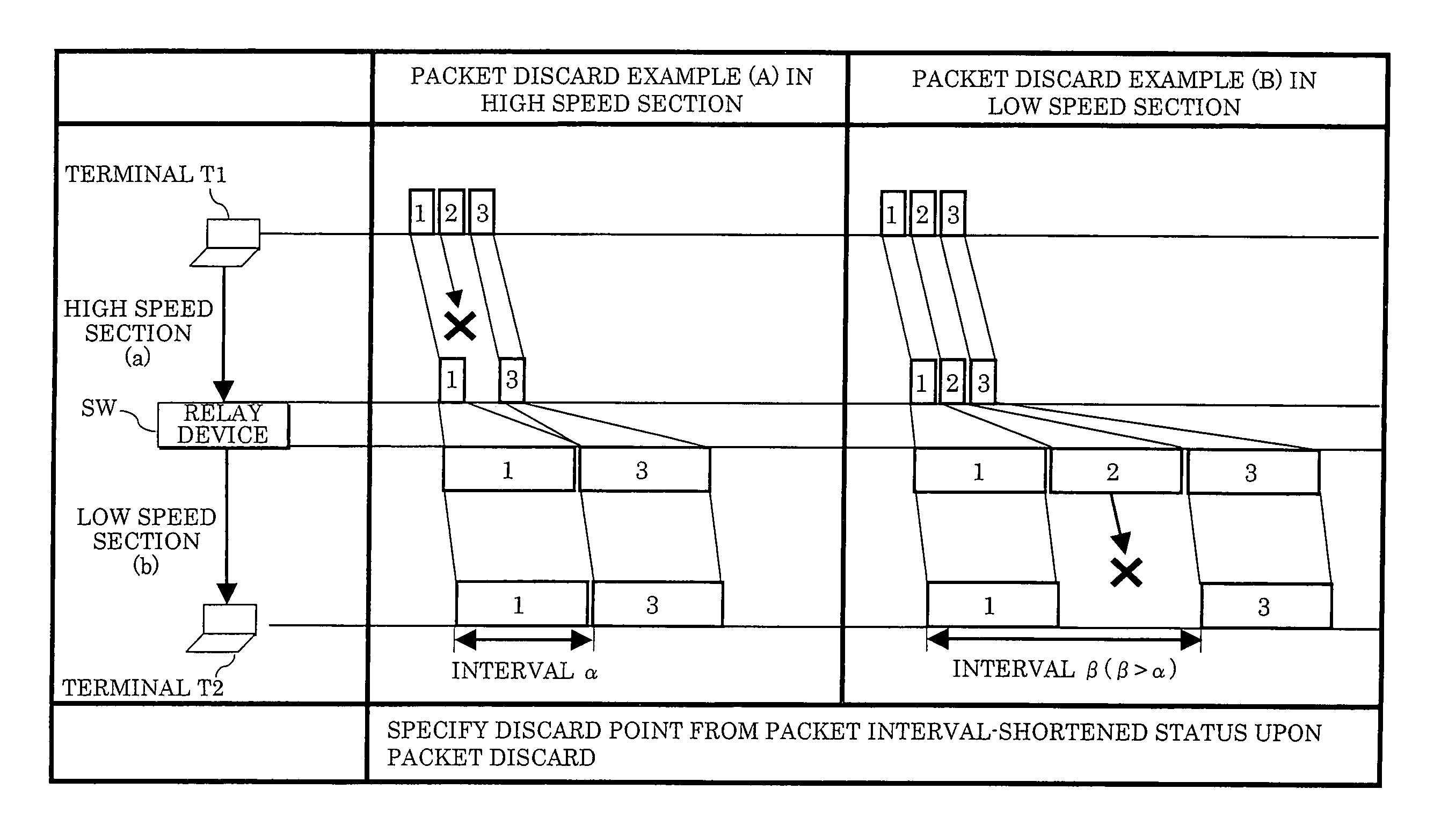
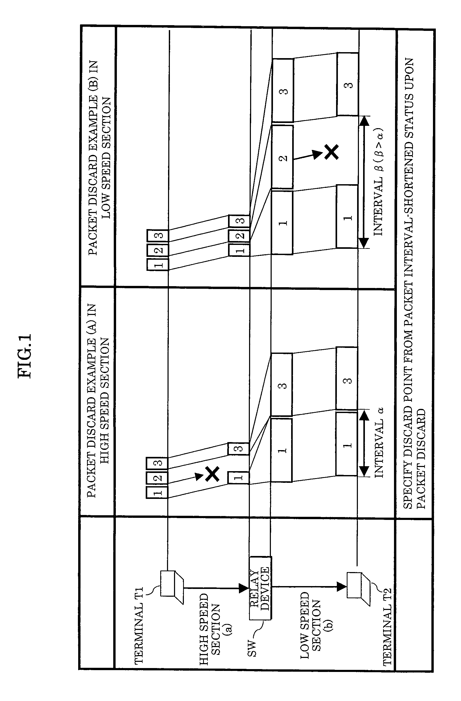
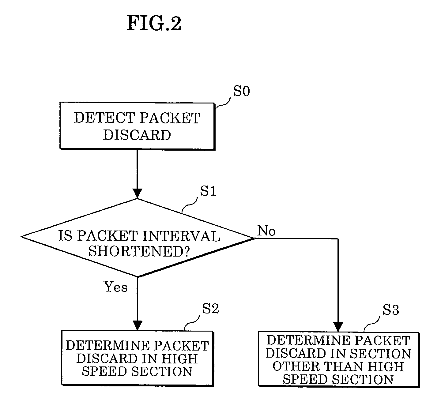
[0108]In this operational embodiment, the packet discard point probing is performed based on the fact that the packet interval is shortened only when the packet discard has occurred in the high speed section (1) upon sequentially transmitting the packets between the terminals T1 and T2.

[0109]FIG. 5 shows a packet sequence in a case where no packet discard has occurred. In the example of FIG. 5, the packets of sequence numbers 1-4 (hereinafter, occasionally described as packets 1-4) sequentially transmitted from the transmitting terminal T1 arrive at the receiving terminal T2 through the L2 switches SW1 and SW2 without being discarded. At the terminal T2, it can be detected that no packet discard has occurred since there is found no missing sequence number.

[0110]FIG. 6 shows a packet sequence in a case where the packet discard has occurred in the high speed section (1). In...

operational embodiment (2) (determination by sequential transmission of probing packets : figs.9-12)

Operational Embodiment (2) (Determination by Sequential Transmission of Probing Packets: FIGS. 9-12)

[0114]In this operational embodiment, the packet discard point probing is performed by noticing that the packet interval is shortened only when the probing packets are sequentially transmitted and the packet discard has occurred in the high speed section in the up direction. In this operational embodiment (2), both of the transmission processing and the packet discard point determination processing are performed at the transmitting terminal T1 shown in FIG. 4.

[0115]FIG. 9 shows a packet sequence in a case where no packet discard has occurred in the same way as the operational embodiment (1) of FIG. 5. As shown in FIG. 9, the packets 1-4 transmitted from the probing terminal T1 are transmitted to the probed terminal T2 through the L2 switches SW1 and SW2. The terminal T1 having received probing response packets 1-4 from the terminal T2 can recognize that no packet discard has occurred ...

operational embodiment (4) (determination by a large size probing packet : figs.17-20)

Operational Embodiment (4) (Determination by a Large Size Probing Packet: FIGS. 17-20)

[0125]In this operational embodiment, the packet discard point probing is performed by noticing that as for a probing packet (e.g. ping request / response packet of 15,000 bytes) having a size large enough to cause an IP fragment, the packet interval is shortened when the packet discard has occurred in the high speed section in the down direction, the packet interval is unshortened when the packet discard has occurred in the low speed section in the down direction, and the probing response itself is not returned when the packet discard has occurred in either high or low speed section in the up direction.

[0126]FIG. 17 shows a packet sequence in a case where no packet discard has occurred when a ping request packet Req divided into packets 1-4 is transmitted from the probing terminal T1 to the probed terminal T2. As shown in FIG. 17, all of the packets 1-4 are received at terminal T2 and the ping reque...


PUM


Abstract

In a relay device or the like in which a speed changes from a high speed to a low speed, a packet residence (packet transfer wait) occurs when a packet string in which packet intervals are shortened arrives. When a packet discard occurs before passing through the relay device or the like, a packet interval having been lengthened by the packet discard is shortened by the relay device or the like for transferring packets. When a packet discard occurs after passing through the relay device or the like, a packet interval having been lengthened by the packet discard remains unshortened for transferring packets. Therefore, by observing at terminals the packet discard and the packet interval on the occasion of the packet discard, whether the packet discard has occurred in the high speed section or the low speed section is specified.

Description

BACKGROUND OF THE INVENTION[0001]1. Field of the Invention[0002]The present invention relates to a packet discard point probing method and device, and in particular to a method and device for detecting a packet discard fault in a network fault probing field.[0003]2. Description of the Related Art[0004]Methods for specifying a packet discarded section generally include two methods of performing a discard point probing by utilizing “ping” from a remote location and of inspecting communication between two locations by packet capturing.[0005]The former probing method is performed by designating an IP address (layer 3) of a probed object with a router being as a probing boundary to measure a discard ratio.[0006]In the latter probing method utilizing packet capturing, packets communicated between two devices are captured and the packets transmitted / received are compared, thereby specifying the discarded point or location.[0007]Additionally, there is a network relay device which, in order ...

Claims


Application Information

Patent Timeline
Patent Type & Authority Patents(United States)
IPC IPC(8): H04J1/16H04L69/40
CPCH04L47/10H04L47/13H04L47/22H04L2001/0097
Inventor YASUIE, TAKESHINOMURA, YUJINOJIMA, SATOSHI
Owner FUJITSU LTD
Why Eureka
Try Eureka