Method and apparatus for mapping the trajectory in the subsurface of a borehole

a technology of trajectory mapping and borehole, which is applied in the field of mapping the trajectory of a borehole, can solve the problems of small diameter borehole, unpredictable wandering along the length of the borehole, and the need for complex instrumentation of the bvm-01 device, so as to achieve a simple and low cost approach.

Inactive Publication Date: 2008-06-17
SCINTREX LTD
View PDF8 Cites 9 Cited by
  • Summary
  • Abstract
  • Description
  • Claims
  • Application Information

AI Technical Summary

Benefits of technology

[0014]As will be appreciated, similar to the BVM-01 vector magnetometer borehole probe, the subject method and apparatus utilize a combination of tiltmeter and vector magnetic component measurements to determine the orientation of a borehole. Advantageously, the subject method and apparatus require only a single component tiltmeter and a single component magnetic field sensor to determine the same information about the orientation of the borehole as is determined using the prior art BVM-01 vector magnetometer borehole probe. It is clear that the subject method and apparatus provide a simpler and lower cost approach to determining borehole orientation.

Problems solved by technology

Small diameter boreholes, such as are commonly employed in mining programs, are subject to unpredictable wanderings along their length.
The BVM-01 device, however, requires complex instrumentation.
All of the above devices suffer from one or more limitations, such as high capital cost, cumulative errors, drifts, instrument complexity or inefficiency in operation.

Method used


Image

  • Method and apparatus for mapping the trajectory in the subsurface of a borehole
  • Method and apparatus for mapping the trajectory in the subsurface of a borehole

Examples


Embodiment Construction

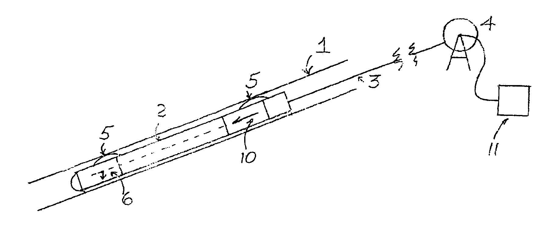
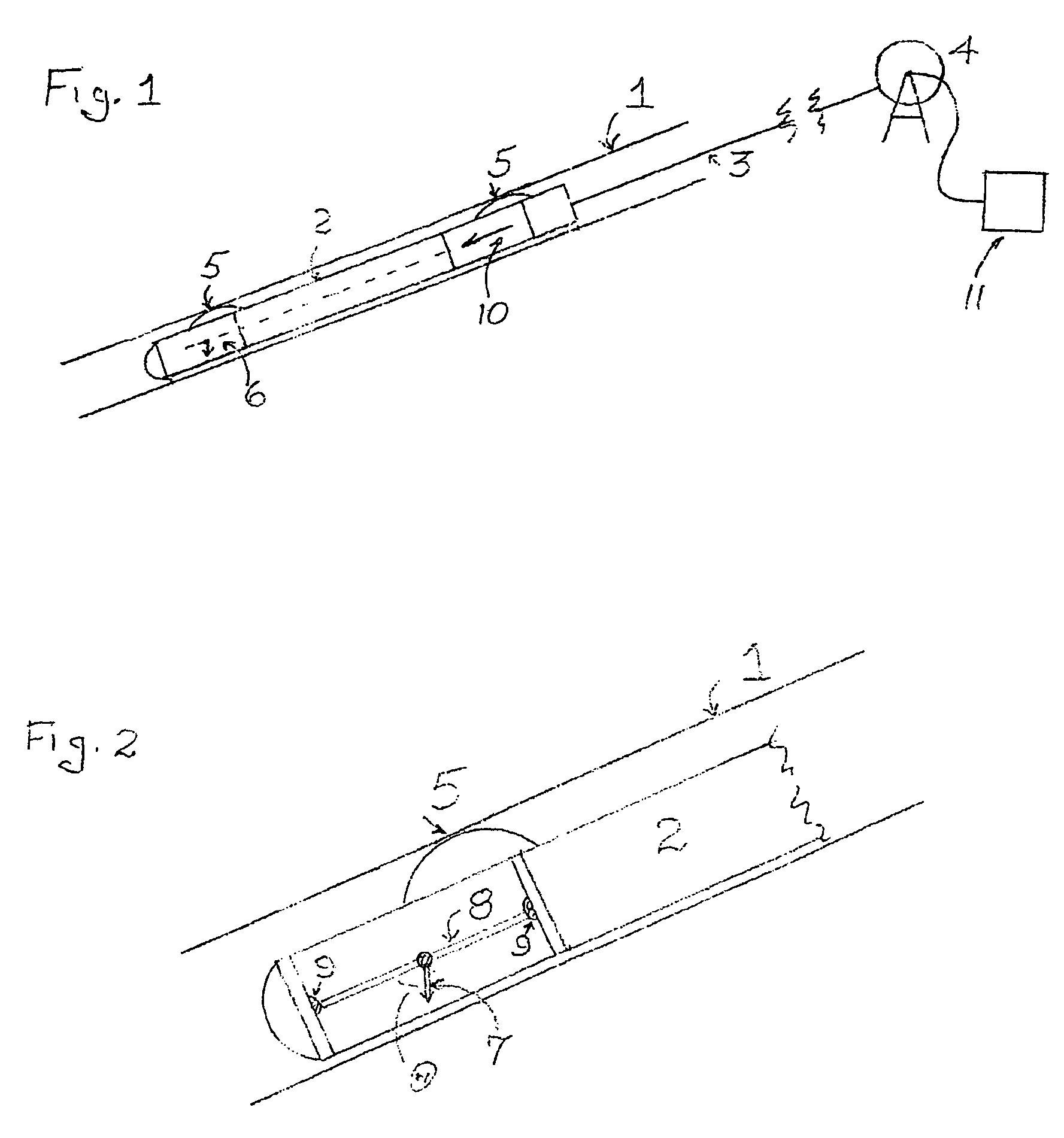
[0018]In FIGS. 1 and 2, item 1 is a borehole in which a sonde 2 has been lowered by means of a cable 3 wound on a winch 4. The sonde 2 is pressed firmly against one side of the borehole by longitudinally spaced springs 5. The sonde 2 contains two devices, namely a tiltmeter 6, whereby the inclination of the sonde 2 (and therefore of the borehole 1) relative to the vertical is measured. There are several suitable types of tiltmeters. In the present embodiment as shown in FIGS. 1 and 2, the tiltmeter 6 is based on a pendulum 7, mounted in a shaft 8, which is free to rotate with ball-bearings 9 within the sonde 2, so that the pendulum weighted side lies on the vertical plane containing the axis of the borehole 1. In this fashion, the pendulum 7 is constrained to rotate within this vertical plane, and thus accurately measures the angle of dip θ of the axis of the sonde 2 (and the borehole 1), relative to the vertical. The tiltmeter 6 is so designed as to provide an electrical output fro...


PUM


Abstract

An apparatus for determining the orientation of a borehole at a point along the borehole, includes a tiltmeter for measuring the inclination of the borehole relative to the vertical, a vector magnetic sensor for measuring the amplitude of the component of the Earth's magnetic field along the axis of the borehole, and means for computing the orientation of the tubular sonde from the measurements of inclination and amplitude of the component of the Earth's magnetic field aligned with axis of the sonde.

Description

FIELD OF THE INVENTION[0001]The present invention relates to mapping of the trajectory of a borehole and in particular to a method and apparatus for determining the orientation of a borehole at a point along the borehole.BACKGROUND OF THE INVENTION[0002]Small diameter boreholes, such as are commonly employed in mining programs, are subject to unpredictable wanderings along their length. For strategic and economic reasons, it is often vital to determine their true trajectories in the subsurface. Only in this way is it possible to obtain a valid three-dimensional picture of the subsurface geology, and, in particular, the true parameters of any mineral deposit whose economic potential is being evaluated.[0003]Various approaches have been made to date to provide the means for determining borehole trajectories. These approaches include, for example, the following: gyroscopes, bending of light in a long tube, tiltmeter and compass and combined tiltmeter and three component magnetometer de...

Claims


Application Information

Patent Timeline
Patent Type & Authority Patents(United States)
IPC IPC(8): E21B47/022
CPCE21B47/022
Inventor SEIGEL, HAROLD O.
Owner SCINTREX LTD
Why Eureka
Try Eureka