Heating device for a fluid line and method of manufacture

a fluid line and heating device technology, applied in the direction of heater elements, machine/engines, service pipe systems, etc., can solve the problems of reducing the efficiency of internal combustion engines, unable to use modern engines, and icing up or blocking the opening of the fluid line of the crankcase ven

Inactive Publication Date: 2008-06-17
DAVID & BAADER DBK
View PDF18 Cites 11 Cited by
  • Summary
  • Abstract
  • Description
  • Claims
  • Application Information

AI Technical Summary

Benefits of technology

[0018]This solution is constructively simple and facilitates the space-saving fitting of the heating device on the fluid line in that the heating element is simply inserted into the well of the outer wall. This solution also simplifies installation and maintenance, because the heating element only has to be inserted into the pocket or taken out of it complete with the holding device.
[0033]In yet another embodiment, the outer wall can exhibit at least one guide element by which the heating device is guided in an insertion direction during installation or during removal. The guide element prevents the heating device from slipping or shifting on the fluid line. At least one guide element can be provided on the heating device to interact with the at least one guide element on the fluid line on the device. A groove extending in the direction of the well is possible, for example, as the guide element.

Problems solved by technology

In some cases this can even lead to the icing up or blockage of the opening of the fluid line of the crankcase vent.
In addition, the pistons are subjected to increased work against the high pressure in the crankcase, leading to a reduction in the efficiency of the internal combustion engine.
A disadvantage with the heating device of DE-A-2432782 is primarily the large space requirement which renders its use with modern engines almost impossible.
In addition, the heating device in DE-A-2432782 is difficult to install and difficult to replace should damage occur.
Although the space requirement with the devices of U.S. Pat. No. 5,970,962 and U.S. Pat. No. 6,062,206 is less than with the heating device of DE-A-2432782, their complicated manufacture and their poor accessibility on the internal combustion engine are disadvantages during servicing.

Method used


Image

  • Heating device for a fluid line and method of manufacture
  • Heating device for a fluid line and method of manufacture
  • Heating device for a fluid line and method of manufacture

Examples


Embodiment Construction

[0060]In the following description, certain specific details are set forth in order to provide a thorough understanding of various embodiments of the invention. However, one skilled in the art will understand that the invention may be practiced without these details. In other instances, well known structures associated with heating devices or fluid lines have not been shown or described in detail to avoid unnecessarily obscuring descriptions of the embodiments of the invention.

[0061]Unless the context requires otherwise, throughout the specification and claims which follow, the word “comprise” and variations thereof, such as, “comprises” and “comprising” are to be construed in an open, inclusive sense, that is as “including, but not limited to.”

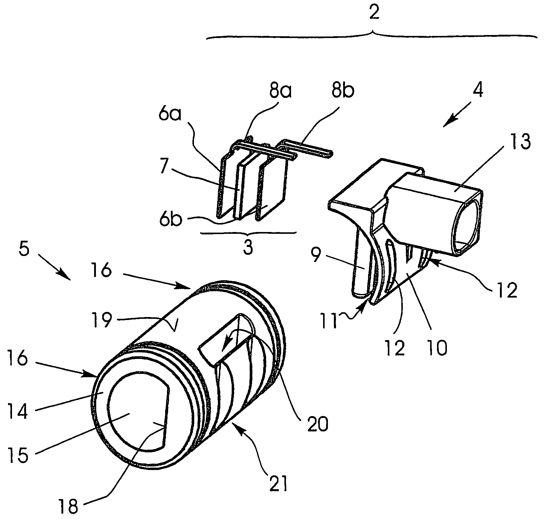
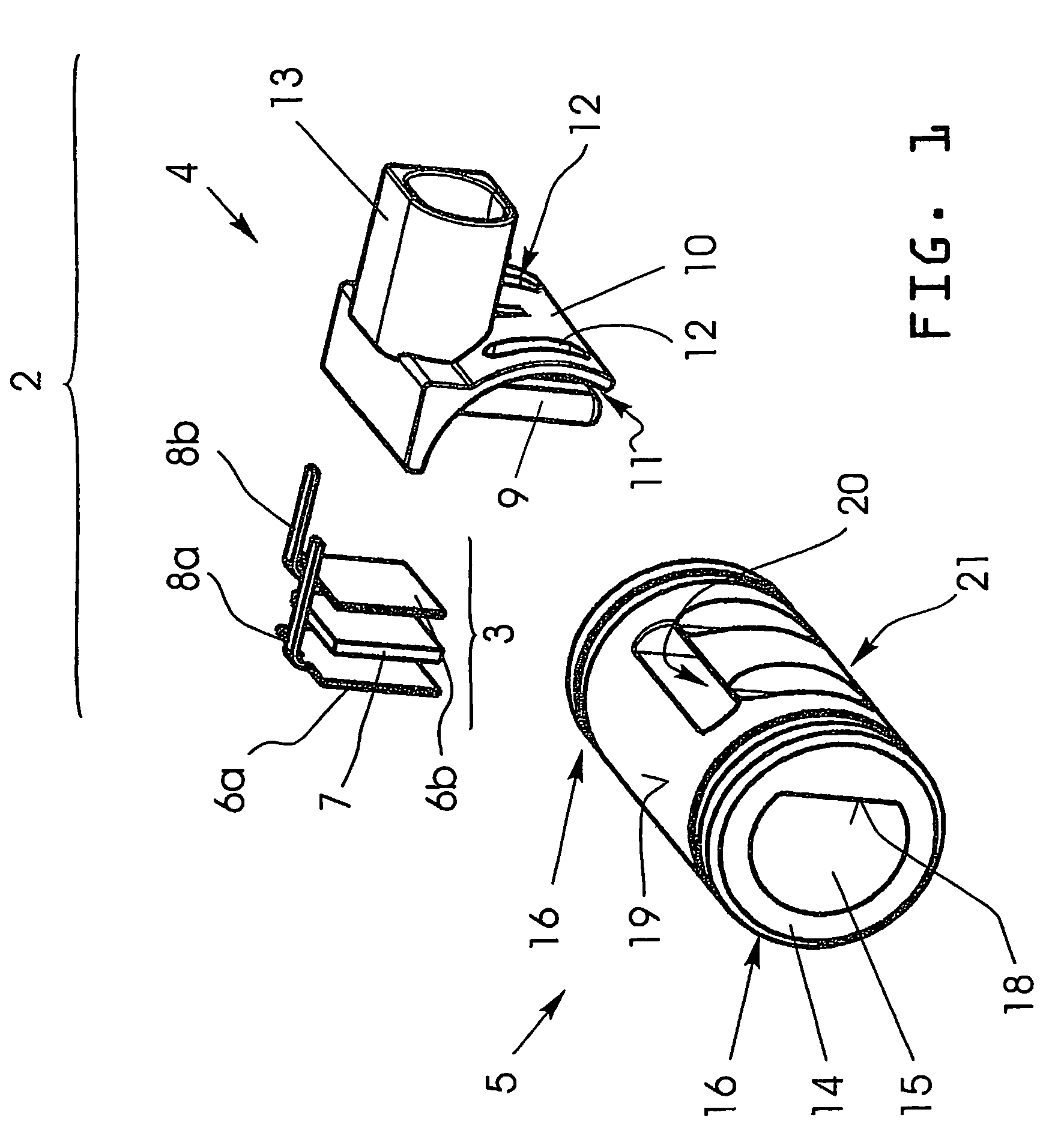
[0062]Firstly, the construction of a first embodiment of a heating module according to one embodiment of the invention is explained for a crankcase venting system of an internal combustion engine based on the exploded representation of FIG. 1...


PUM


Abstract

Embodiments of the present invention relate to a heating device for a fluid line, in particular for a crankcase venting system in an internal combustion engine, with a heating element and with a holding device, through which the heating element can be mounted on the fluid line. Embodiments of the invention also relate to a fluid line for the accommodation of the said heating device and to a heating module with a fluid line and a heating device fitted to it. Embodiments of the invention also relate to a method for the manufacture of the heating device mentioned above.

Description

BACKGROUND OF THE INVENTION[0001]1. Field of Invention[0002]The present invention generally relates to a heating device for a fluid line, in particular for a crankcase venting system in an internal combustion engine, with a heating element and with a holding device, through which the heating element can be mounted on the fluid line. The invention also relates to a fluid line for the accommodation of the said heating device and to a heating module with a fluid line and a heating device fitted to it. Finally, the invention also relates to a method for the manufacture of the heating device mentioned above.[0003]2. Description of the Related Art[0004]In modern internal combustion engines, vents are provided for the crankcase which houses the crank mechanism with the crankshaft, the connecting rods and the pistons as well as the cylinders. The crankcase is sealed on the cylinder side by one or more cylinder heads and underneath a sump pan is normally joined to the crankcase.[0005]When th...

Claims


Application Information

Patent Timeline
Patent Type & Authority Patents(United States)
IPC IPC(8): F02M25/06E03B7/12F01M13/00F16L53/35F16L53/38
CPCF01M13/00F16L53/005F16L53/008H05B3/06H05B3/24F01M2013/0027H05B2203/02H05B2203/022F16L53/35F16L53/38
Inventor GSCHWIND, THOMASBEETZ, KLAUS
Owner DAVID & BAADER DBK
Why Eureka
Try Eureka