Bearing insert sleeve for roller cone bit

a technology of bearing insert and roller cone, which is applied in the direction of shafts, bearings, cutting machines, etc., can solve the problems of uneven contact stress, small misalignment of the bearing surface of the cone bearing with the bearing pin, and the influence of the load on the bit seal between the cone and the bearing pin for sealing lubrican

Active Publication Date: 2008-06-17
BAKER HUGHES INC
View PDF22 Cites 73 Cited by
  • Summary
  • Abstract
  • Description
  • Claims
  • Application Information

AI Technical Summary

Benefits of technology

[0039]The invention has significant advantages. The floating and non-rotating sleeve reduces points of high contact stress in the bearing due to tilting or cocking of the cone when loaded. In the second embodiment, the sleeve also reduces high stress concentrations that might otherwise occur to the lubricant seal.

Problems solved by technology

Even though the clearances between the bearing surfaces are quite small, slight misalignment of the cone bearing surface with the bearing pin tends to occur.
This slight misalignment can result in uneven contact stress.
The seal between the cone and the bearing pin for sealing lubricant is also affected by the load imposed on the bit.
Varying seal contact pressure can be caused by misalignment of the cone bearing surface and bearing pin.
Changes in contact pressure can cause excessive heat in certain areas of the seal, shortening the life.

Method used


Image

  • Bearing insert sleeve for roller cone bit
  • Bearing insert sleeve for roller cone bit
  • Bearing insert sleeve for roller cone bit

Examples


first embodiment

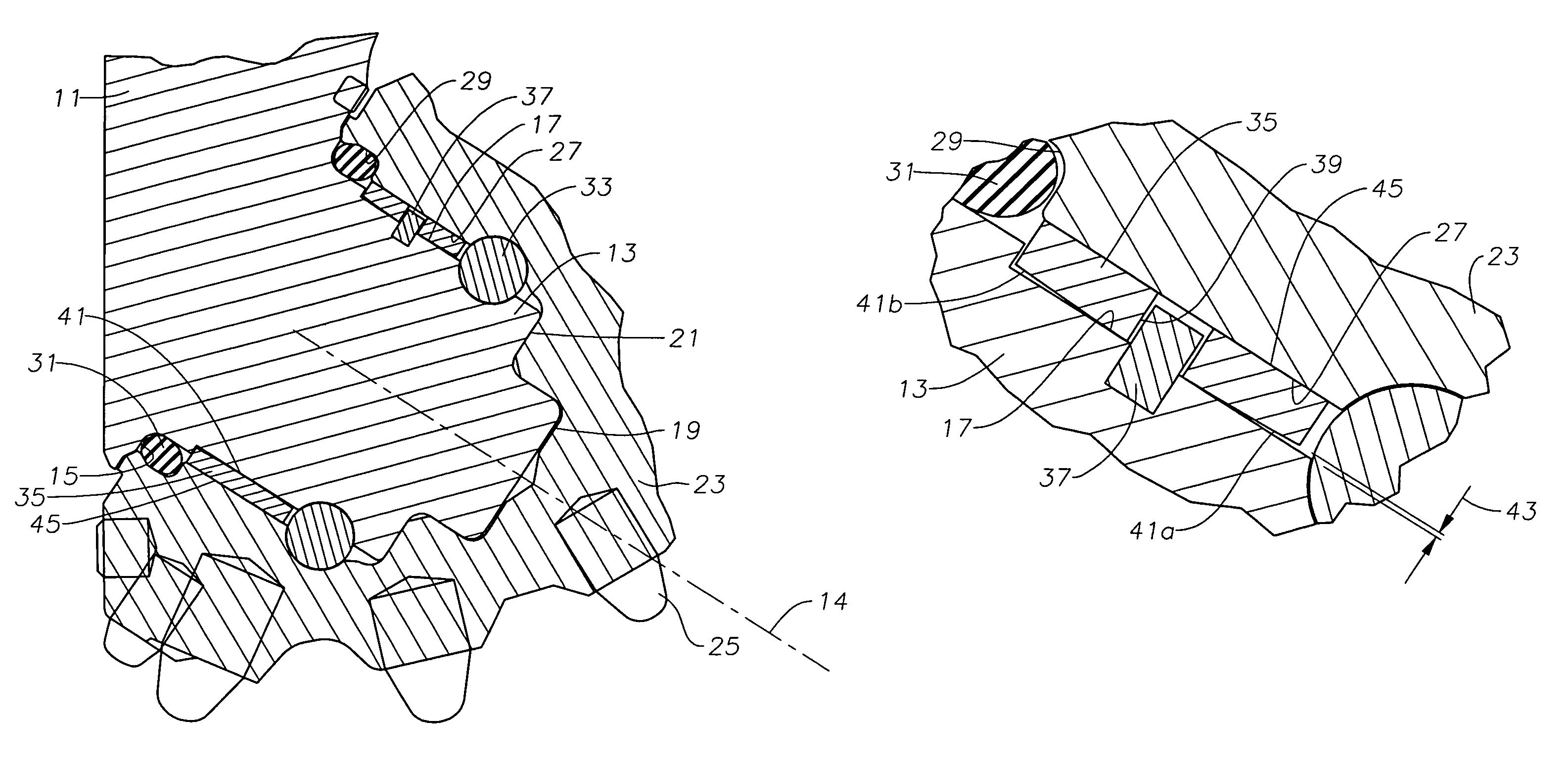
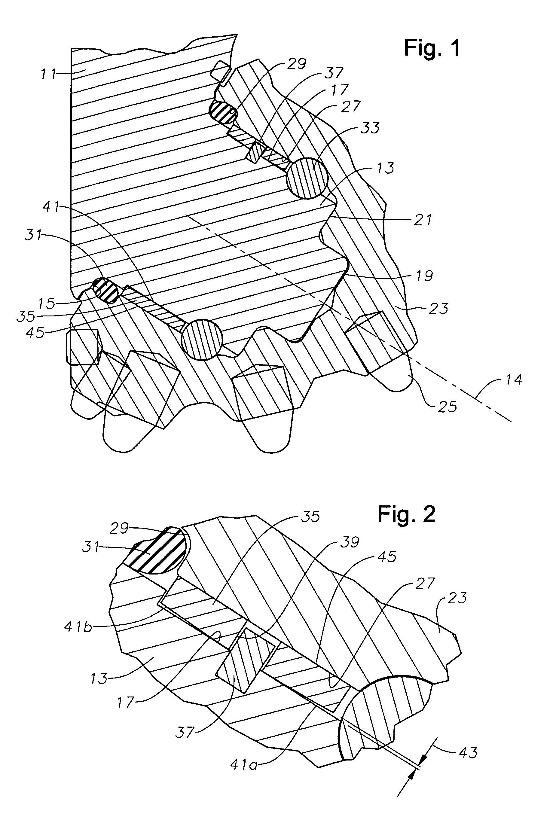
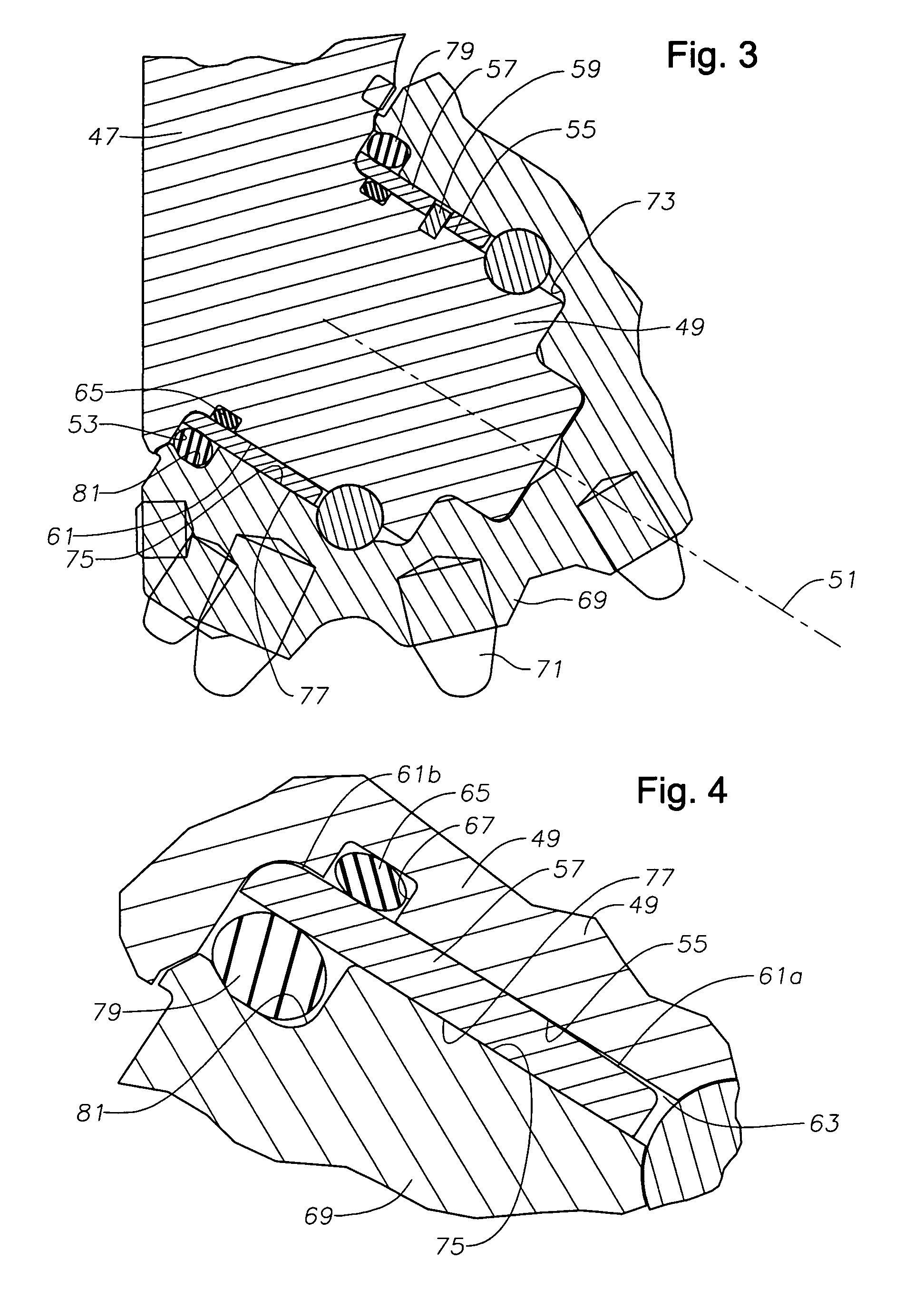
[0025]In this embodiment, insert 57 also comprises a sleeve 57 mounted on bearing pin 49. Sleeve 57 is constructed generally the same as in the first embodiment, except that it extends substantially to last machined surface 53. Sleeve 57 is secured against rotation by a pin 59. Sleeve 57 has an inner surface 61 with a conical forward portion 61a and a conical rearward portion 61b, each converging to a midpoint area. A clearance 63 between inner surface 61 and bearing pin central surface 55 converges from each end of sleeve 57 to a minimum inner diameter in the central area when the bit is unloaded. In this embodiment, an inner seal 65 seals the inner diameter of sleeve 61 to bearing pin 49. Inner seal 65 is preferably located within a groove 67 formed on bearing pin 49 near its rearward end.

[0026]Cone 69 may be the same as cone 23 of the first embodiment, having cutting elements 71 and a cavity 73. Cavity 73 has a cylindrical bearing surface 75 that slidingly engages a sleeve bearin...

second embodiment

[0039]The invention has significant advantages. The floating and non-rotating sleeve reduces points of high contact stress in the bearing due to tilting or cocking of the cone when loaded. In the second embodiment, the sleeve also reduces high stress concentrations that might otherwise occur to the lubricant seal.


PUM


Abstract

An earth boring bit has a bearing pin with a sleeve mounted on it. The sleeve is fixed against rotation but able to float relative to the bearing pin. A cone fits over and forms a bearing surface with the sleeve. The sleeve and bearing pin are configured to have a clearance between them that has a forward portion that progressively decreases in a rearward direction. The clearance progressively decreases in a forward direction from the rearward end of the sleeve. The cone and the sleeve are able to tilt in unison with each other relative to the bearing pin when the bit is loaded.

Description

FIELD OF THE INVENTION[0001]This invention relates in general to rolling cone earth-boring bits, and in particular to an insert ring that is mounted between the bearing pin and the cone bearing surfaces.BACKGROUND OF THE INVENTION[0002]A typical roller cone earth-boring bit has a bit body with three bit legs. A bearing pin extends from each bit leg, and a cone rotatably mounts on the bearing pin. The bearing surfaces between the cavity of the cone and the bearing pin are filled with lubricant. A seal is located between the cone and the bearing pin to seal lubricant within and keep drilling fluid from entering.[0003]During operation, a high downward force is imposed on the drill bit from the weight of the drill string. The downward force transmits through the bit body and bearing pin to the cone. Even though the clearances between the bearing surfaces are quite small, slight misalignment of the cone bearing surface with the bearing pin tends to occur. This slight misalignment can res...

Claims


Application Information

Patent Timeline
Patent Type & Authority Patents(United States)
IPC IPC(8): E21B10/22
CPCE21B10/22E21B10/25
Inventor ZAHRADNIK, ANTON F.KOLTERMANN, TERRY J.NGUYEN, DON Q.DICK, AARON J.SULLIVAN, ERICSHU, SCOTT SHIQIANG
Owner BAKER HUGHES INC
Why Eureka
Try Eureka