Apparatus and method for electrical immobilization weapon

a technology of immobilization weapon and apparatus, which is applied in the direction of white arms/cold weapons, weapons, electric shock equipment, etc., can solve the problems of increasing the spread of immobilization weapon, increasing the risk of projectiles missing targets, and reducing incapacitating efficiency, so as to reduce the vibration of immobilized projectiles, increase the efficiency of immobilization weapon, and reduce the target point

Active Publication Date: 2008-01-01
VOLGER INT AB
View PDF12 Cites 97 Cited by
  • Summary
  • Abstract
  • Description
  • Claims
  • Application Information

AI Technical Summary

Benefits of technology

[0014]It is another object of the present invention to provide an improvement which can be easily adapted for use by a conventional weapon to increase its effective shooting range.
[0027]Unlike the conventional weapon which can only be held vertically straight, the present invention will allow the weapon to be turned substantially level to the ground. The stunning result will be equally effective even if just one projectile hit a target in the front. In this case, a force movement is created between the target and the other projectile, and instead of moving forward the projectile is forced to move inward around the body of the target and hit the target on the side or the back, thus reacts a “hugging effect” of the weapon. To minimize the vibration of the projectiles when they are being restrained by the filament and to achieve maximum result of said “hugging effect”, in preferred embodiments the filament or thread can be connected to locations on the projectiles which are at or close to their center of gravity and preferably a bit forward. Each projectile can have at least one spiky or hooked head section and an elongated body section, and the head section could have multiple contacting heads with same electric polarity of the weapon's power supply to increase its efficiency. One benefit of such horizontal deployment is that the targeting point can be lowered by few inches without fearing reduction of weapon's accuracy, especially when a target is at a great distance. It would also reduces the potential risk of ventricular fibrillation and asphyxia, which, according to several articles, could happen even after the stun current is ceased, by avoiding the chest organs as much as possible. The horizontal firing of both projectiles also suffers less from angular gravitational effect compared to vertical firing of which at least one projectile would be launched downwardly. Alternatively, the projectiles can be designed to have a fixed horizontal configuration in the cartridge. In such case, instead of having substantially the same vertical plane between the projectiles and the cartridge as for a conventional weapon, the projectiles will have a horizontal plane which is substantially perpendicular to the vertical plane of the cartridge. Preferably, one projectile is positioned horizontally at one side of the vertical plane of the cartridge to form a first angle between said projectile and the vertical plane of the cartridge and the other projectile positioned horizontally at the other side to form a second angle. The sum of said first and second angle define the intersect angle between the two projectiles and the said two angles are preferably equal to each other. Said intersect angle in this case is preferably formed at the vertical medial plane and / or along the horizontal medial plane of the cartridge.

Problems solved by technology

However, the increase in spreading for improved effectiveness is not without limit.
For example, a space between the projectiles greater than 25 inches would not only increase the risk of the projectiles missing the target but also would be likely to reduce its incapacitating efficiency.
As a consequence, the projectiles cannot reach an adequate spacing of at least 5 inches after leaving the cartridge for close range effectiveness.
However, the improvement for close range effectiveness is compromised by the reduced long range effectiveness since the excessive spreading will lead the projectiles to miss a more remote target.
Thus, the compact configuration of the weapon and the angular arrangement of the projectiles in the prior art result in a relatively limited operational shooting range.
As can be noticed, when a target is within a close range of 4 feet to the weapon, the spread of the projectiles would not deliver satisfactory disabling result since the space between the projectiles have not reached the minimum 7 inches, while at a distance longer than 15 feet the projectiles would most likely miss the target because of the excessive spreading of the projectiles relative to a human body or small animal.
Further increase of the angle is highly undesirable since it will drastically reduce the long-range effectiveness.
The limited effective shooting range of such weapons, both minimum and maximum range, is a serious drawback and could cause dangerous consequences.
While outside this range, both at close and long shooting range, the effectiveness would deteriorate and a subject could gain at least partial mobility while being shocked.
To adapt for the changing spreading between the projectiles, the common practices have been to increase the weapons overall power output or prolong its electrical discharge durations or both, which, although would compensate for the deterioration, could result in the electric overload to a subject when the spreading is within the optimal range and render the weapon more dangerous.
In this case, however, the advantage of relatively improved effective shooting range gives way to a rather bulky body structure.
Furthermore, the plurality of projectiles deliver multiple open circuits on a target, and complete return circuits back to the weapon through more than one gap between the projectiles, which will significantly increase the weapon's power consumption and reduce its battery life circle.
Still, the maximum effectiveness of this configuration depends on all projectiles impact on the target, and if all projectiles do impact on a target, the maximum effectiveness would be just as much as if only the projectile on the highest point and the one on the lowest impacted on the target with the longest gap; while if one or both projectiles, which is normally the lowest ones, miss the target, its advantage would be lost.
In such case, only the two electric opposed projectiles on the upper side have the effective power while the ones below become useless.
The latter increases the angular spreading effects and its downward velocity greatly increases its descent due to the gravitational force, which is one of the main causes for limited effective long shooting range.
In addition, weapons disclosed in the prior art require that they must be held straight in order for the two projectiles to be arranged in the vertical direction to achieve the desired result, since turning the weapon at all will further increase the risk of causing the projectiles to miss the target.
In addition, the projectile on the upper side is normally targeted at the center of the chest of a human body and there is a risk that its hooked sharp head will cause serious injuries to important organs such as eyes, throat, cervical artery and nerve in case of panic or other mistakes.

Method used


Image

  • Apparatus and method for electrical immobilization weapon
  • Apparatus and method for electrical immobilization weapon
  • Apparatus and method for electrical immobilization weapon

Examples


Embodiment Construction

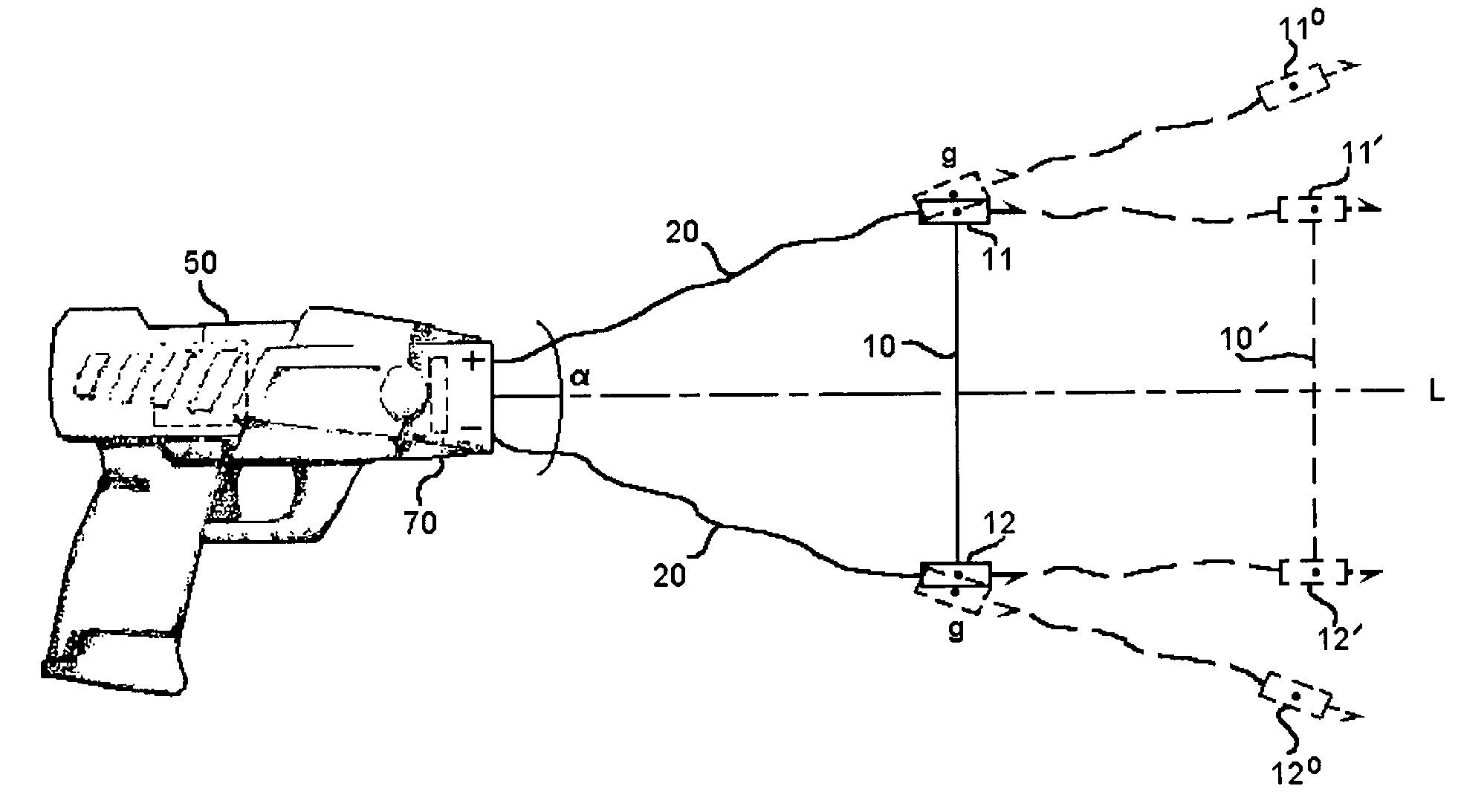
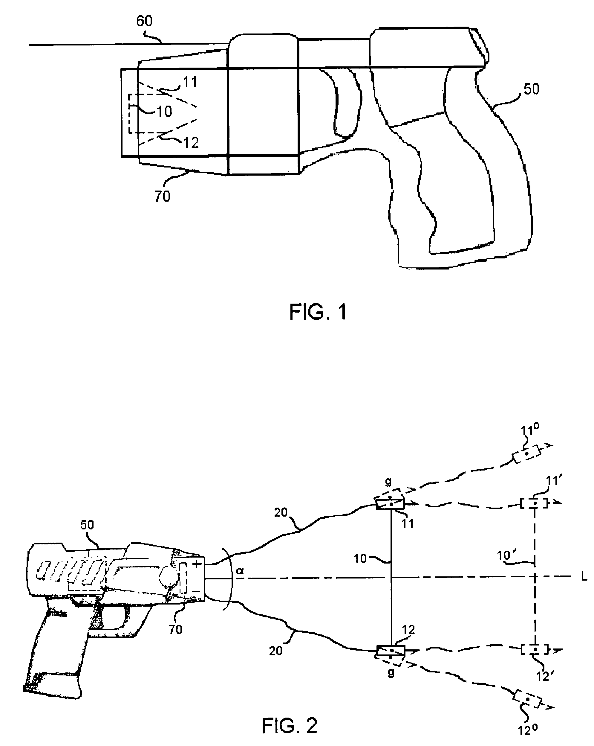
[0034]Referring now to FIG. 1, there is provided an outlined illustration of an electrical immobilization weapon in conjunction with a preferred embodiment of the present invention, which mainly comprises a body section (50) and at least one cartridge apparatus (70). In this case the cartridge is inserted. The weapon utilizes a type of high-tension power supply (not shown) which could be any suitable power supply already known to the art. The single cartridge in this case contains two projectiles (11, 12) along a vertical plane of the cartridge (70) as shown with dotted lines. A single filament or thread (10) is interconnected to the two projectiles (11, 12) to form a kinetic unit, which can be launched by a common propellant. The said propellant could be any suitable types commercially available, for examples spring devices, compressed air, compressed CO2, explosive or pyrotechnic. The weapon can be designed to be single or multiple fired. Because of its compact size, other accesso...


PUM


Abstract

An electrical immobilization weapon having a prolonged range of effectiveness and improved accuracy compared to conventional Taser weapons, while being compact in structure and lightweight. The weapon having a replaceable cartridge which, when employed, can space a pair of electrodes to a specific critical area on a remote target, so the electrical energy carried by the electrodes can induce the involuntary contraction of the involved muscles through the critical area within a significant range of length between the electrodes for effective immobilization. The electrical energy generated by a power source of the weapon completes an electrical circuit through a minimum path being a length of at least 5 inches between the two points on the target.

Description

BACKGROUND OF THE INVENTION[0001]1. Field of Invention[0002]The present invention generally relates to a type of immobilization weapon which impart high-tension electricity to disable and capture, and more particularly to such a type of weapon which employs at least one cartridge for launching two tailing-wired spreading apart electrical projectiles, to impact a living target and to discharge said high-tension electricity between the two points of the projectiles. The present invention provides improvement over the prior art to significantly increase the effectiveness and accuracy of such weapons.[0003]2. Prior Arts[0004]Weapons for immobilization and capture are generally referred to as “Stun guns”. Such devices basically consist of a launch section and a body section, of which the launch section normally contains at least one single cartridge apparatus while the body section mainly accommodates the stun gun electronics and battery compartment. The electronic circuits of the weapon...

Claims


Application Information

Patent Timeline
Patent Type & Authority Patents(United States)
IPC IPC(8): H05C1/00F42B30/00
CPCF41B11/62F41H13/0025
Inventor SU, LI
Owner VOLGER INT AB
Why Eureka
Try Eureka