Acoustic resonator performance enhancement using alternating frame structure

a technology of alternating frame structure and resonator, which is applied in the direction of piezoelectric/electrostrictive/magnetostrictive devices, electrical apparatus, impedence networks, etc., can solve the problem of reducing the quality factor (q) of the filter

Active Publication Date: 2008-06-17
AVAGO TECH INT SALES PTE LTD
View PDF261 Cites 270 Cited by
  • Summary
  • Abstract
  • Description
  • Claims
  • Application Information

AI Technical Summary

Problems solved by technology

These modes can result in a decreased quality factor (Q) for the filter.

Method used


Image

  • Acoustic resonator performance enhancement using alternating frame structure
  • Acoustic resonator performance enhancement using alternating frame structure
  • Acoustic resonator performance enhancement using alternating frame structure

Examples


Embodiment Construction

[0023]In the following Detailed Description, reference is made to the accompanying drawings, which form a part hereof, and in which is shown by way of illustration specific embodiments in which the invention may be practiced. In this regard, directional terminology, such as “top,”“bottom,”“front,”“back,”“leading,”“trailing,” etc., is used with reference to the orientation of the Figure(s) being described. Because components of embodiments of the present invention can be positioned in a number of different orientations, the directional terminology is used for purposes of illustration and is in no way limiting. It is to be understood that other embodiments may be utilized and structural or logical changes may be made without departing from the scope of the present invention. The following detailed description, therefore, is not to be taken in a limiting sense, and the scope of the present invention is defined by the appended claims.

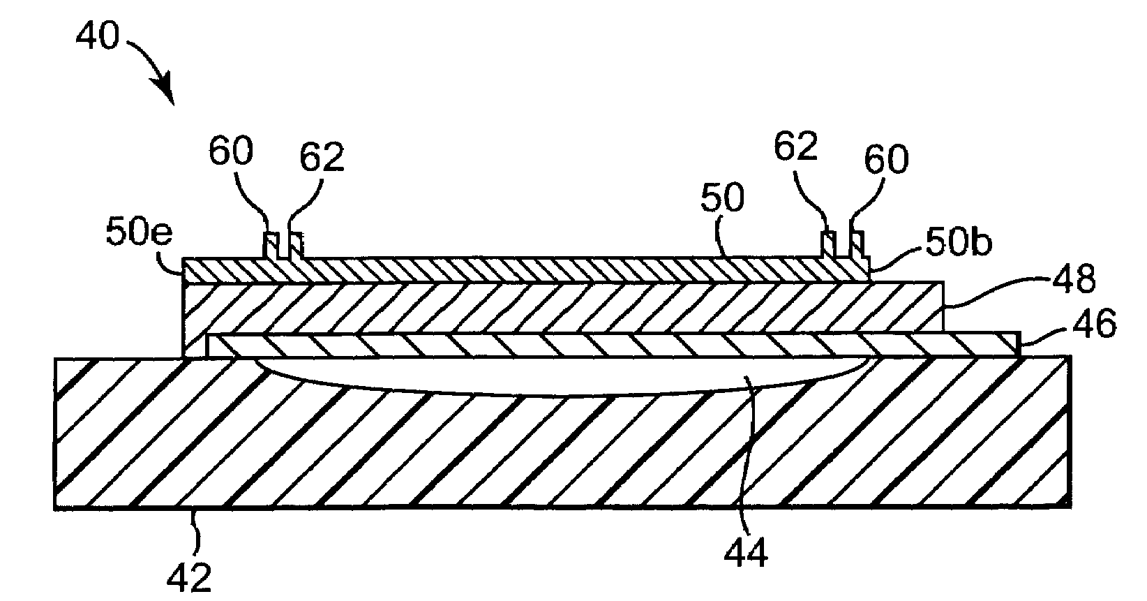
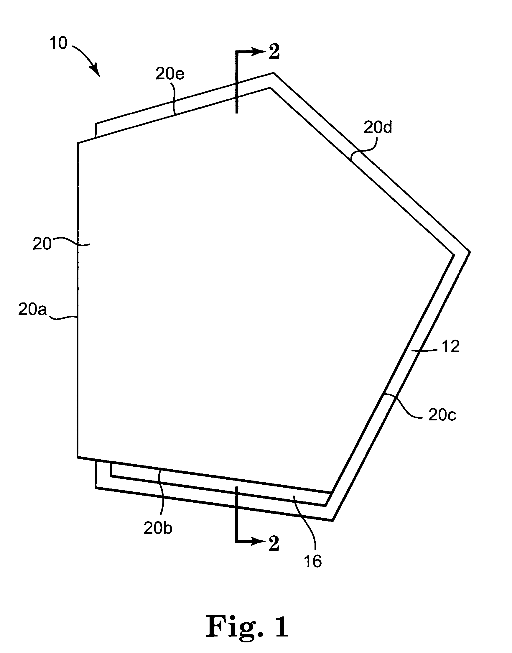
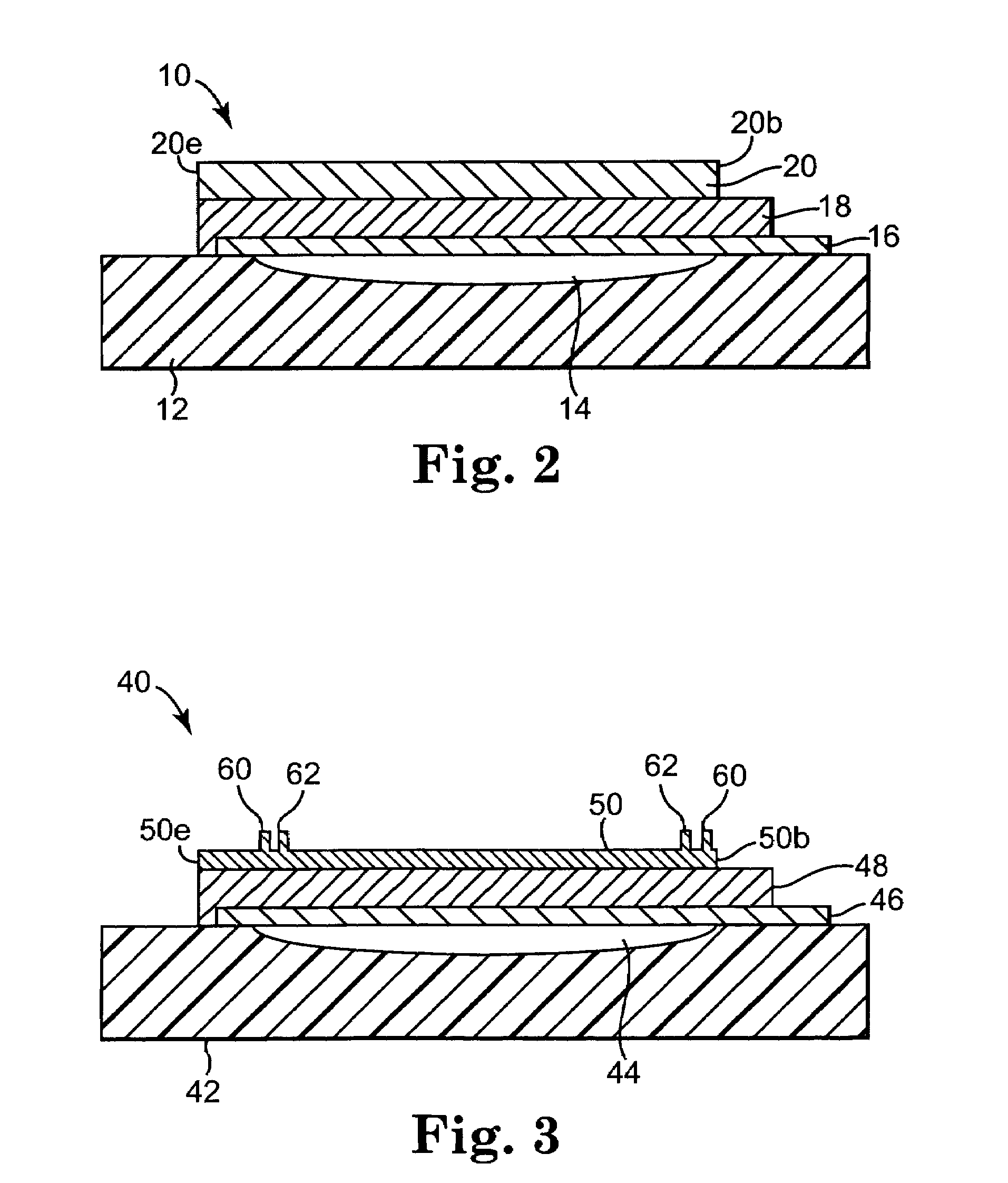
[0024]FIGS. 1 and 2 illustrate top and cross-sectiona...


PUM


Abstract

Disclosed is an acoustic resonator that includes a substrate, a first electrode, a layer of piezoelectric material, a second electrode, and an alternating frame region. The first electrode is adjacent the substrate, and the first electrode has an outer perimeter. The piezoelectric layer is adjacent the first electrode. The second electrode is adjacent the piezoelectric layer and the second electrode has an outer perimeter. The alternating frame region is on one of the first and second electrodes.

Description

CROSS-REFERENCE TO RELATED APPLICATIONS[0001]This Patent Application is related to U.S. Pat. No. 7,161,448, filed on Jun. 14, 2004, entitled “ACOUSTIC RESONATOR PERFORMANCE ENHANCEMENT USING SELECTIVE METAL ETCH;” to Utility Patent Application Ser. No. 11 / 100,311, filed on Apr. 6, 2005, entitled “ACOUSTIC RESONATOR PERFORMANCE ENHANCEMENT USING FILLED RECESSED REGION;” to Provisional Patent Application Ser. No. 60 / 615,255, filed on Oct. 1, 2004, entitled “A THIN FILM BULK ACOUSTIC RESONATOR WITH A MASS LOADED PERIMETER; and to Utility Patent Application Ser. No. 10 / 990,201, filed on Nov. 15, 2004, entitled A THIN FILM BULK ACOUSTIC RESONATOR WITH A MASSED PERIMETER, and is commonly assigned to the same assignee as the present invention.BACKGROUND[0002]The need to reduce the cost and size of electronic equipment has created a need for smaller single filtering elements. Thin-Film Bulk Acoustic Resonators (FBARs) and Stacked Thin-Film Bulk Wave Acoustic Resonators (SBARs) represent one...

Claims


Application Information

Patent Timeline
Patent Type & Authority Patents(United States)
IPC IPC(8): H03H9/13H03H9/15H03H9/54H01L41/22H01L41/29
CPCH03H3/02H03H9/02086H03H9/02149H03H9/132H03H9/173H03H9/13H03H2003/0428H03H9/02007H03H9/171H03H9/24
Inventor RUBY, RICHARD C.FAZZIO, RONALD S.FENG, HONGJUNBRADLEY, PAUL D.
Owner AVAGO TECH INT SALES PTE LTD
Why Eureka
Try Eureka