System and method for improved rotor tip performance

a technology of rotor tip and rotor blade, which is applied in the direction of machines/engines, liquid fuel engines, air-flow influencers, etc., can solve the problems of increased drag on the blades of one or more rotor assemblies, unsatisfactory effects, and higher fuel consumption so as to improve the performance of rotary wing aircraft and improve the performance of rotor blades

Inactive Publication Date: 2006-02-09
THE BOEING CO
View PDF16 Cites 86 Cited by
  • Summary
  • Abstract
  • Description
  • Claims
  • Application Information

AI Technical Summary

Benefits of technology

[0007] The present invention comprises systems and methods for the performance enhancement of rotary wing aircraft. In one aspect, a system for improved rotor blade performance in a rotorcraft includes one or more sails having an aerodynamic shape and positioned proximate to a tip of the rotor blade. An actuator may be coupled to the sail that is configured to rotate the sail about a longitudinal axis of the sail, the longitudinal axis extending outwardly from the tip. A control system is operable to receive information from a selected rotorcraft system and to command the actuator to rotate the sail to a position that corresponds to a predetermined favorable rotor blade operating condition. In another aspect, the invention includes a method of operating a rotorcraft including configuring the rotorcraft in a selected flight condition, communicating input signals to a control system operable to position sails coupled to the tips of the blades of a rotor assembly, processing the input signals according to a constraint condition to generate sail positional information, and transferring the sail positional information to the sail.

Problems solved by technology

Due to pressure differences that exist between an upper surface of the blade and a lower surface while the blade is in motion, vortices are generated at the tips of the blades that produce various undesirable effects.
One notable effect is an increase in drag on the blades of the one or more rotor assemblies, particularly while the rotary wing aircraft is stationary, or hovering.
Consequently, an engine that drives the one or more rotor assemblies must develop additional torque to overcome the pressure drag generated by the tip vortices, resulting in higher fuel consumption for the rotary wing aircraft.
Further, since the tips of the blades generally operate at relatively high subsonic local Mach numbers (typically between M=0.6 to 0.95), an increase in compressibility drag may occur that is due to shock wave drag or shock-induced flow separation, particularly on an advancing blade tip when the vehicle is in forward motion.
Another undesirable effect of the tip vortices is the generation of noise and impulsive changes in aerodynamic loads on the blades.
In particular, the interaction of vortices shed from a blade tip and a following blade, and / or the interaction of the tip vortices with the fuselage or empennage structures of the rotary wing aircraft, result in a phenomenon known as blade-vortex interaction (BVI), which may be particularly severe when the blades are relatively heavily loaded, such as during a low-speed descent to landing, or during the execution of certain flight maneuvers.
Since BVI generates elevated vibration levels in various components comprising the rotary wing aircraft, the useful life of such components is typically shortened.
Additionally, occupants in the rotary wing aircraft may experience the unpleasant effects of the elevated vibration levels generated by BVI.
The foregoing devices are generally effective under a specific flight condition, and are relatively less effective under other different flight conditions.

Method used


Image

  • System and method for improved rotor tip performance
  • System and method for improved rotor tip performance
  • System and method for improved rotor tip performance

Examples


Embodiment Construction

[0015] The present invention relates to apparatus and methods for the performance enhancement of rotary wing aircraft. Many specific details of certain embodiments of the invention are set forth in the following description and in FIGS. 1 through 6 to provide a thorough understanding of such embodiments. One skilled in the art, however, will understand that the present invention may have additional embodiments, or that the present invention may be practiced without several of the details described in the following description.

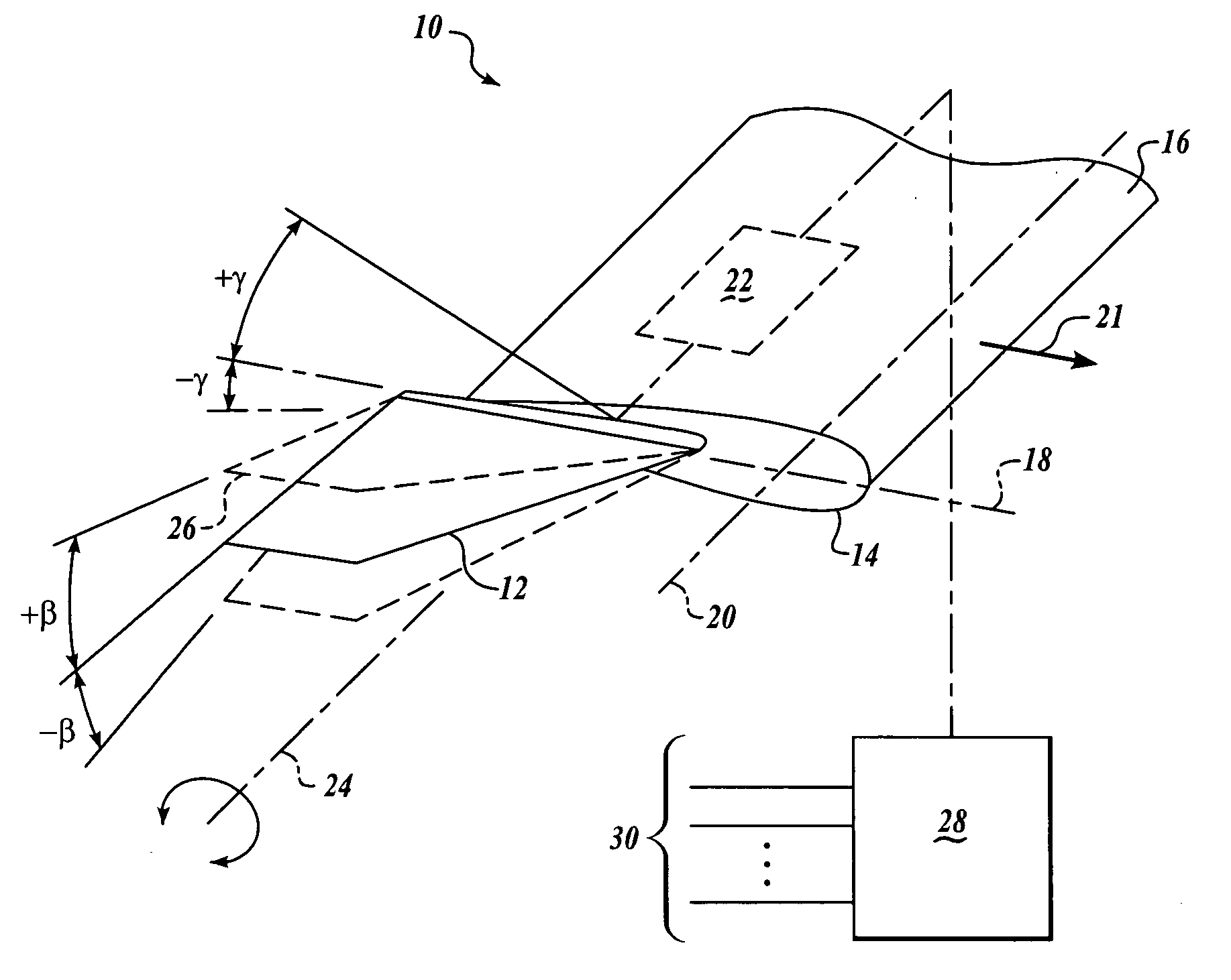
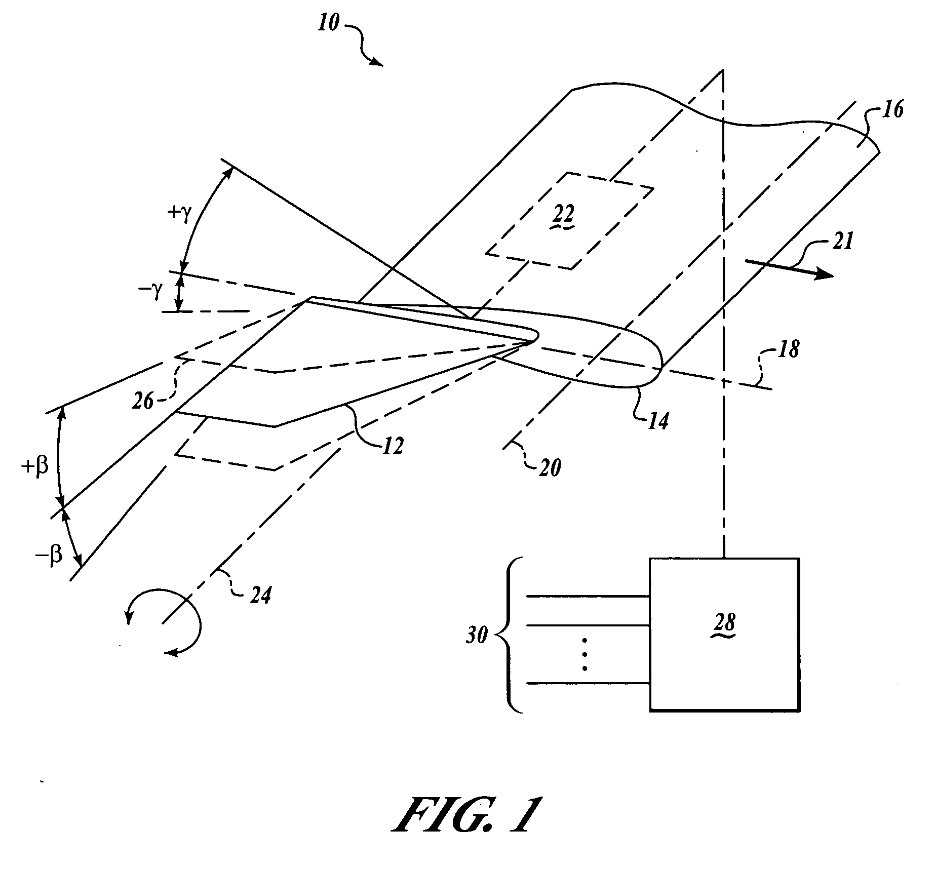
[0016]FIG. 1 is a block diagrammatic, partial isometric view of a system 10 for improved rotor tip performance according to an embodiment of the invention. The system 10 includes at least one sail 12 that is coupled to a tip portion 14 of a rotorcraft blade 16 along a chord 18 of the blade 16. The sail 12 is generally aerodynamically configured, which may include a sweep back angle relative to a longitudinal axis 20 of the blade 16. Additionally, the sail 12 m...


PUM


Abstract

The present invention discloses systems and methods for the performance enhancement of rotary wing aircraft through reduced torque, noise and vibration. In one embodiment, a system includes a sail having an aerodynamic shape positioned proximate to a tip of the rotor blade. An actuator may be configured to rotate the sail relative to the blade tip. a A control system receives information from a rotorcraft system and commands the actuator to rotate the sail to a predetermined favorable rotor blade operating condition. In another embodiment, a method includes configuring the rotorcraft in a selected flight condition, communicating input signals to a control system operable to position sails coupled to tips of blades of a rotor assembly, processing the input signals according to a constraint condition to generate sail positional information, and transferring the sail positional information to the sail.

Description

FIELD OF THE INVENTION [0001] This invention relates generally to rotary wing aircraft, and more particularly to apparatus and methods for the performance enhancement of rotary wing aircraft. BACKGROUND OF THE INVENTION [0002] It is well known that rotary wing aircraft are capable of flight in a vertical direction as well as forwardly or backwardly in horizontal flight, and may further remain stationary while aloft. Examples of rotary wing aircraft correspondingly include helicopters and tilt-rotor aircraft, among others. In all of these flight vehicles, thrust is generated by one or more rotor assemblies having aerodynamically-shaped blades that are constantly in rotational motion relative to the flight vehicle. The generated thrust may be used to lift and / or propel the rotorcraft in a lateral direction. Due to pressure differences that exist between an upper surface of the blade and a lower surface while the blade is in motion, vortices are generated at the tips of the blades that...

Claims


Application Information

Patent Timeline
Patent Type & Authority Applications(United States)
IPC IPC(8): B64C27/54
CPCB64C23/065Y02T50/164B64C27/463B64C23/072Y02T50/10
Inventor BUSSOM, RICHARDMCVEIGH, MICHAEL A.NARDUCCI, ROBERT P.ZIENTEK, THOMAS A.
Owner THE BOEING CO
Why Eureka
Try Eureka