Method, system and program product for providing a configuration specification language supporting selective presentation of configuration entities

a configuration specification and language technology, applied in the field of computer-aided design, simulation and configuration of digital devices, can solve the problems of inability to centralize configuration latches for all similar functional units, tedious creation and maintenance, and inability to maintain accurate configuration documentation

Active Publication Date: 2008-06-17
META PLATFORMS INC
View PDF55 Cites 20 Cited by
  • Summary
  • Abstract
  • Description
  • Claims
  • Application Information

AI Technical Summary

Benefits of technology

[0019]All objects, features, and advantages of the present invention will become apparent in the following detailed written description.

Problems solved by technology

Although it is certainly possible to test a digital design by actually building the digital design, digital designs, particularly those implemented by integrated circuitry, are typically verified and debugged by simulating the digital design on a computer, due in part to the time and expense required for integrated circuit fabrication.
However, because transmission latency via intra-chip wiring is not decreasing proportionally to the increase in the operating frequency of functional logic, it is generally viewed as undesirable to centralize configuration latches for all similar functional units.
Conventionally, configuration latches and their permitted range of values have been specified by error-prone paper documentation that is tedious to create and maintain.
Compounding the difficulty in maintaining accurate configuration documentation and the effort required to set configuration latches is the fact that different constituencies within a single company (e.g., a functional simulation team, a laboratory debug team, and one or more customer firmware teams) often separately develop configuration software from the configuration documentation.
As the configuration software is separately developed by each constituency, each team may introduce its own errors and employ its own terminology and naming conventions.
Consequently, the configuration software developed by the different teams is not compatible and cannot easily be shared between the different teams.
In addition to the foregoing shortcomings in the process of developing configuration code, conventional configuration software is extremely tedious to code.
In particular, the vocabulary used to document the various configuration bits is often quite cumbersome.
Another problem encountered in the simulation and debugging of simulated and hardware digital systems is that the state of the simulated or hardware digital system is difficult to present in a convenient format.
Although this convention technique of ascertaining the state of a digital design reduces the difficulty in parsing and interpreting the results of a system “dump,” the individuals responsible for debugging the design are often unaware of the details of the underlying latches and configuration constructs and are therefore left to “reverse engineer” much of the design to understand its operation, or seek assistance from the original design team.
Moreover, because the names of the signals and latches within a design often change between revisions of the design, the scripts and other debugging tools developed to interpret the state of the system and facilitate debugging cannot be reused for multiple designs.

Method used


Image

  • Method, system and program product for providing a configuration specification language supporting selective presentation of configuration entities
  • Method, system and program product for providing a configuration specification language supporting selective presentation of configuration entities
  • Method, system and program product for providing a configuration specification language supporting selective presentation of configuration entities

Examples


Embodiment Construction

[0076]The present invention employs a configuration specification language and associated methods, systems, and program products for configuring and controlling the setup of a digital system (e.g., one or more integrated circuits or a simulation model thereof). In at least one embodiment, configuration specifications for signals in the digital system are created in HDL code by the designer responsible for an associated design entity. Thus, designers at the front end of the design process, who are best able to specify the signal names and associated legal values, are responsible for creating the configuration specification. The configuration specification is compiled at model build time together with the HDL describing the digital system to obtain a configuration database that can then be utilized by downstream organizational groups involved in the design, simulation, and hardware implementation processes.

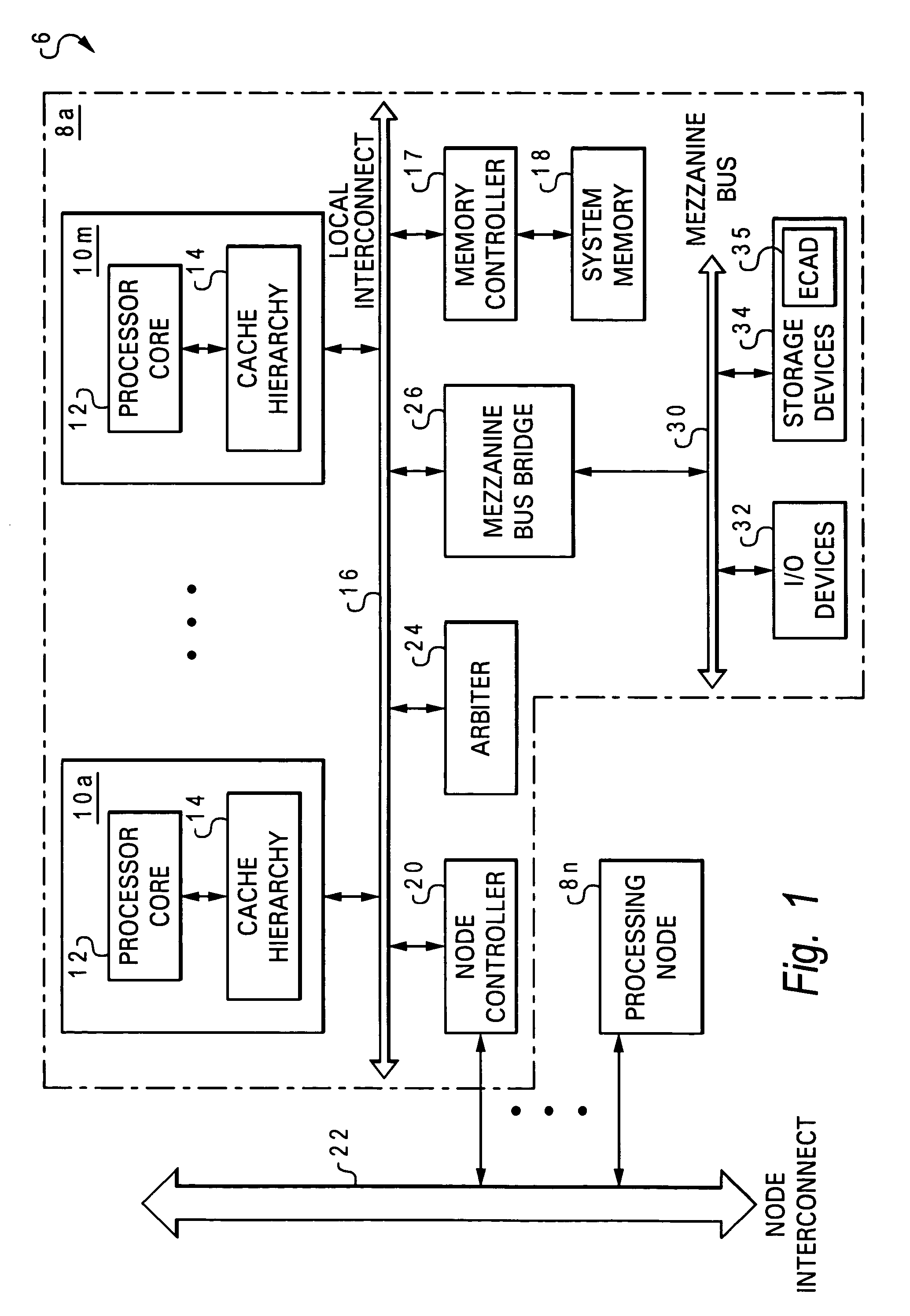
[0077]With reference now to the figures, and in particular with reference to FI...


PUM


Abstract

In at least one hardware definition language (HDL) file, at least one design entity containing a functional portion of a digital system is specified. The design entity logically contains a latch having a respective plurality of different possible latch values. With one or more statements, a configuration entity is associated with the latch. The configuration entity has a plurality of different settings and each setting reflects which value is loaded in the associated latch. A controlling value set, indicating at least one controlling value for which presentation of a current setting of the configuration entity instance is restricted, is also defined in one or more files. Thereafter, in response to a request to present at least a partial state of the digital system, a current setting of the configuration entity instance is excluded from presentation by reference to a configuration database indicating the controlling value set.

Description

CROSS-REFERENCE TO RELATED APPLICATION[0001]The present application is related to U.S. patent application Ser. No. 10 / 902,628, which is assigned to the assignee of the present invention and incorporated herein by reference in its entirety.BACKGROUND OF THE INVENTION[0002]1. Technical Field[0003]The present invention relates in general to designing, simulating and configuring digital devices, modules and systems, and in particular, to methods and systems for computer-aided design, simulation, and configuration of digital devices, modules and systems described by a hardware description language (HDL) model.[0004]2. Description of the Related Art[0005]In a typical digital design process, verifying the logical correctness of a digital design and debugging the design (if necessary) are important steps of the design process performed prior to developing a circuit layout. Although it is certainly possible to test a digital design by actually building the digital design, digital designs, pa...

Claims


Application Information

Patent Timeline
Patent Type & Authority Patents(United States)
IPC IPC(8): G06F17/50G06F9/44
CPCG06F17/5022G06F30/33
Inventor ROESNER, WOLFGANGWILLIAMS, DEREK EDWARD
Owner META PLATFORMS INC
Why Eureka
Try Eureka