Torque limiting device for an electric motor

a technology of torque limit and electric motor, which is applied in the direction of electric controller, dynamo-electric converter control, instruments, etc., can solve the problems of screw, insertion tool and/or workpiece damage, etc., and achieve the effect of faulty screwing, unacceptably high torque and faulty way

Active Publication Date: 2007-06-26
ROBERT BOSCH GMBH
View PDF11 Cites 76 Cited by
  • Summary
  • Abstract
  • Description
  • Claims
  • Application Information

AI Technical Summary

Benefits of technology

[0008]When the torque limiting device is designed in accordance with the present invention it has the advantage that the maximum value of the motor current which is provided from a torque nominal value setting, is determined in dependence on the rotary speed of the electric motor, whereby the torque peaks possible due to the kinetic energy of the rotating masses and occurring in hard screwing case can be included in the regulating and / or turning off criterium. For this purpose, additionally to a detection device for the motor current received during the operation of the motor, a rotary speed detection device is available. The rotary speed detected by the rotary speed detection device and the motor current registered by the current detection device are transmitted to a control and / or regulating device which places these parameters in a relation relative to one another.
[0009]In accordance with a setting of a maximum permissible torque, the control and / or regulating device determines a maximum motor current which is produced in presence of a predetermined rotary speed for a predetermined, maximum permissible torque, which must not be exceeded, so that the predetermined maximum permissible torque is not exceeded when the torque peak resulting from the rotating masses under load comes up.
[0017]In another embodiment the rotary speed detecting device derives the rotary speed during the operation of the electric motor from such parameters as a motor voltage and a motor current, calculates them or reads a table or a curve stored in an electronic component. In this way advantageously a mechanical or a partial mechanical rotary speed detection is not needed, and no changes or structural operations in the electrical-mechanical construction, in particular the drive line between the motor and the force take off point are needed. In particular, in this embodiment an integration of the invention in the existing machines and devices is possible, that have an electric motor with a torque which must not exceed a predetermined maximum value.
[0019]A preferable embodiment of the invention resides in its use in electric tools, for example electric screwdrivers For this purpose in a very advantageous manner damages to a tool or a workpiece or faulty screwing due to undesired exceeding of a maximum torque permissible during the application are avoided. The invention can be integrated in the known electric tools, since due to the electrical operation, they it does not change the principle mechanical and electrical construction of the tool. This is especially the case when the rotary speed determination is performed on the basis of the electrical variables, such as a motor current and a motor voltage. Moreover, it can be provided that a product row, for example an electric tool with the invention, is performed in another, electrically and mechanically otherwise identical way, wherein in a very advantageous manner the available production capabilities can be used in an optimal manner.

Problems solved by technology

Depending on the area of application of the tool and / or the properties of the material to be treated and / or workpiece, it is frequently required that a predetermined torque must not be exceeded on the insertion tool, since otherwise the damages and / or destruction of the insertion tool or the workpiece can occur.
When the end position of the screwing is reached from a high rotary speed, so that the screw head mechanically limits the further rotation of the screw, the screw, insertion tool and / workpiece can be damaged, or the screwing can be performed with an unacceptably high torque and thereby in a faulty way.
In unfavorable cases, the material structure of the screw and / or insertion tool and / or workpiece can be overloaded with the suddenly occurring torque peaks so great, that the material structure breaks up.
Mechanical safety couplings of this type have the disadvantage that they allow only a very inaccurate and in some cases only stepped adjustment of the maximum permissible torque.
They further have a disadvantage that they are susceptible to a mechanical wear, and thereby the force transmission decreases in general and with increasing aging of the safety coupling.
The through slippage with the adjusted maximum permissible torque is performed relatively inaccurately and within relatively great error intervals, so that the safety coupling interrupts the drive of the insertion tool at a torque which is lower than the preadjusted torque, and in many cases at reaching a higher torque, whereby a material damage can occur due to a torque-caused overloading.
Such devices operate inaccurately, since in particular at high spindle rotary speeds the torque which is actually occurs at the tool or at the workpiece with reaching of the predetermined motor current due to the predetermined maximum torque, is significantly greater than the adjusted limiting value.
This post running is suddenly braked by the mechanical limit of the screw, which leads to formation of a torque which is independent from the drive.

Method used


Image

  • Torque limiting device for an electric motor
  • Torque limiting device for an electric motor
  • Torque limiting device for an electric motor

Examples


Embodiment Construction

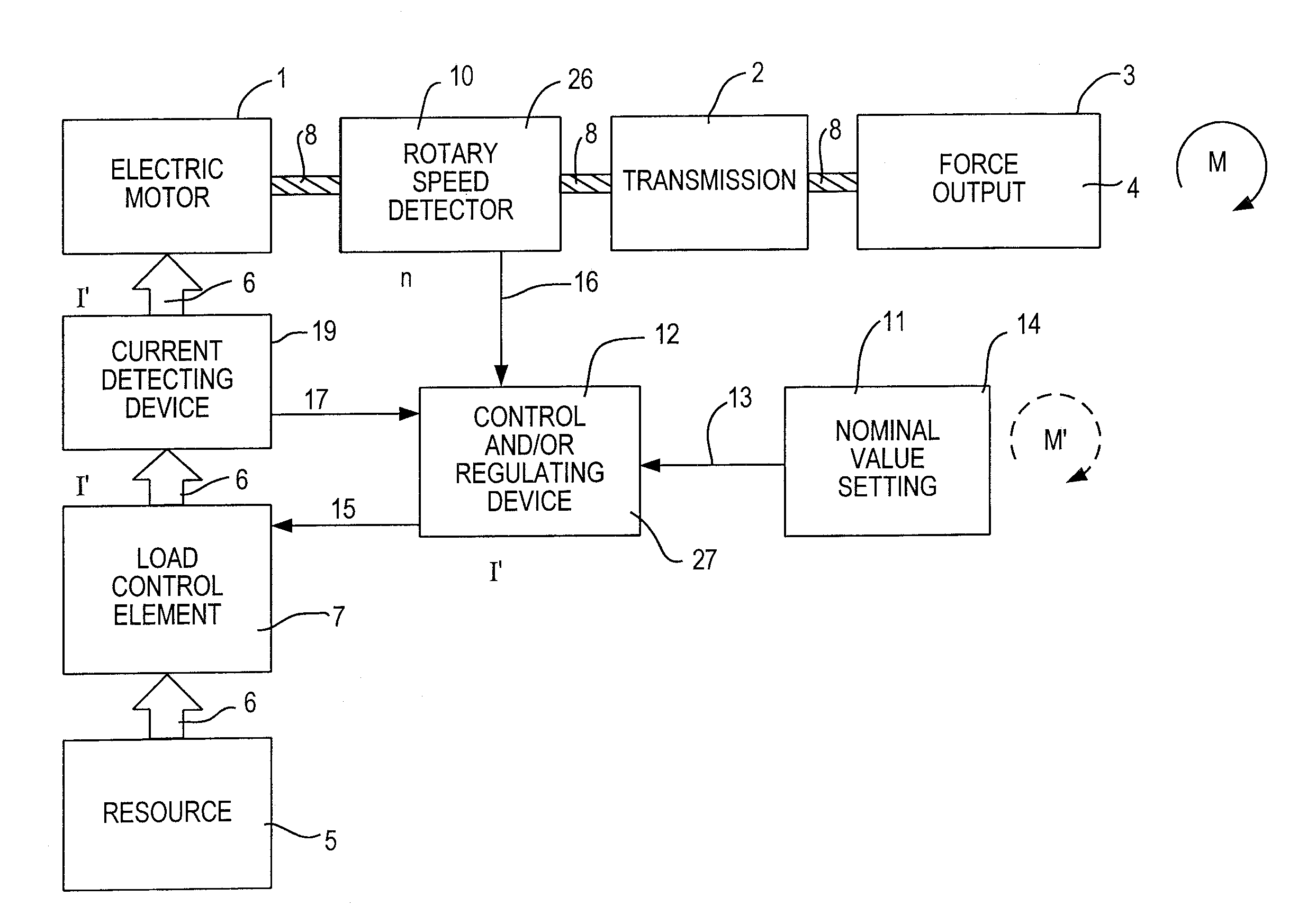
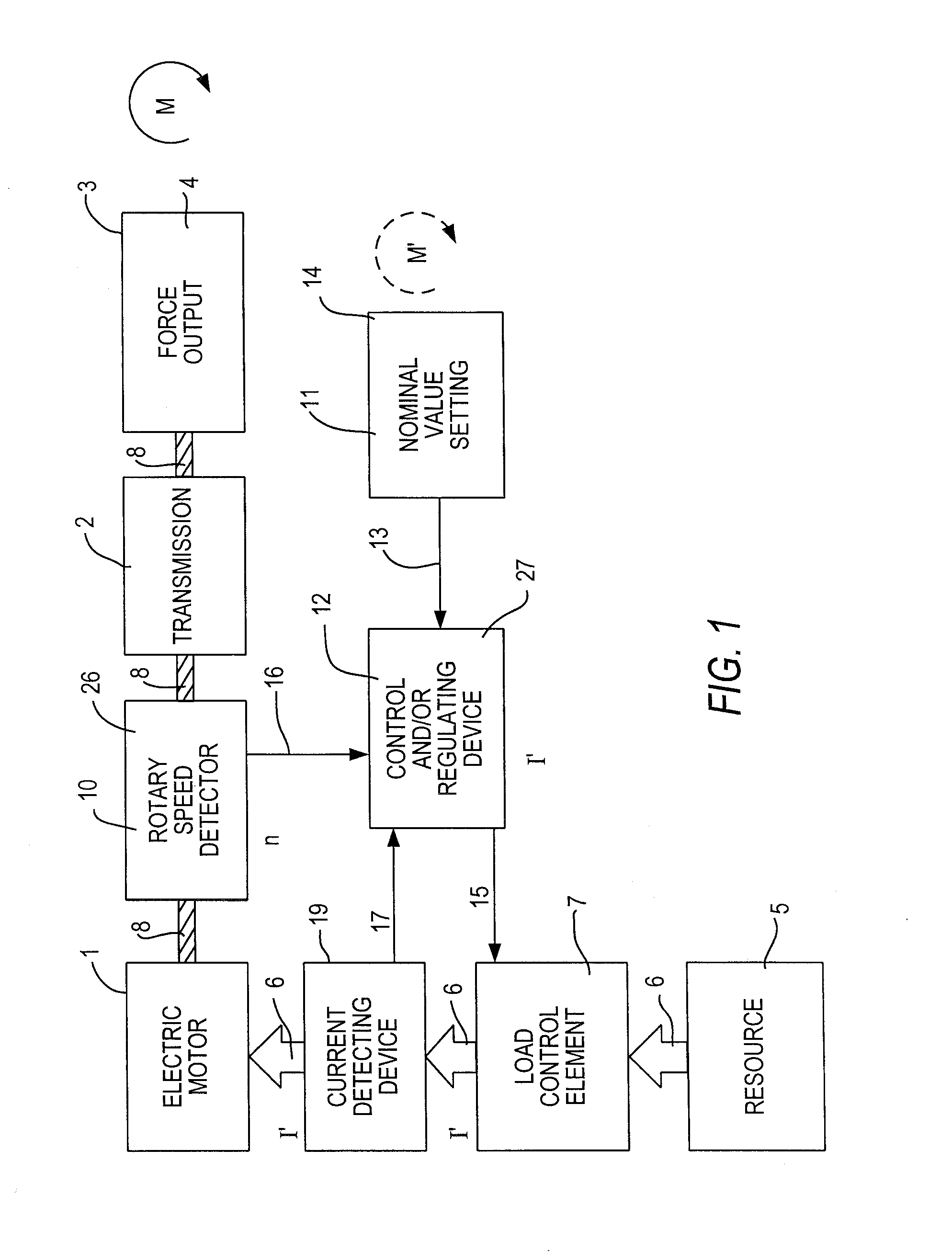
[0025]FIG. 1 shows an electric motor 1 with a transmission 2 and a force output 3 associated therewith. The force output 3 can be formed, for example, as a clamping chuck 4. The drawing further shows a rotary speed detecting device 10 formed as a mechanically coupled rotary speed sensor 26, a current detecting device 9, a nominal value setting 11 formed as an operator element 14, a control and / or regulating device 12, and a load control element 7.

[0026]The operator can fix a maximum torque M′ occurring on the force output 3, by means of the nominal value setting 11 formed as the operating element 14. The maximum permissible torque M′ adjusted by the operator on the nominal value setting 11 is transmitted from it by means of a torque setting signal 13, to the control and / or regulation device 12.

[0027]The electric motor 1 is supplied from a not illustrated electrical energy source 5 with a motor current 6, which passes through the load control element 7. This leads to a start of the e...


PUM


Abstract

A rotary speed limiting device for an electric motor has a current detecting device for detecting a motor current of the electric motor, a nominal value setting for adjusting a torque, a control and / or regulating device which limits the motor current to a maximum value depending on the nominal value setting, a rotary speed detecting device for detecting a rotary speed of the electric motor, the control and / or regulating device determining a maximum value of the motor current depending on the rotary speed determined by the rotary speed detecting device.

Description

BACKGROUND OF THE INVENTION[0001]The present invention relates to a torque limiting device for an electric motor.[0002]Electric motors are used in the most diverse and different areas. For example, the electric motors are used in electric tools and serve for driving an insertion tool. Depending on the area of application of the tool and / or the properties of the material to be treated and / or workpiece, it is frequently required that a predetermined torque must not be exceeded on the insertion tool, since otherwise the damages and / or destruction of the insertion tool or the workpiece can occur. For example, it is known in electric screwdrivers, depending on the density of the material which receives the screws and / or the size or geometry of the screws, to provide a torque increase in the course of the screwing process. In this case a torque can be reached such that the material structure of the screw and / or of the workpiece is loaded so that this material structure breaks up.[0003]Sit...

Claims


Application Information

Patent Timeline
Patent Type & Authority Patents(United States)
IPC IPC(8): H02P7/00B25B23/147H02P3/14H02P7/28
CPCB25B23/147H02P7/28H02P7/00
Inventor BOSCH, VOLKERWIRNITZER, BERND
Owner ROBERT BOSCH GMBH
Why Eureka
Try Eureka